Method and device for observing photoacoustic imaging in single-array element and multi-angle mode based on compressive sensing
A technology of compressed sensing and photoacoustic imaging, applied in sensors, acoustic wave diagnosis, infrasonic wave diagnosis, etc., can solve the problems of poor horizontal image resolution, high hardware cost, serious artifacts, etc., and achieve high resolution, simple operation, and reliability good sex effect
- Summary
- Abstract
- Description
- Claims
- Application Information
AI Technical Summary
Problems solved by technology
Method used
Image
Examples
specific Embodiment approach 1
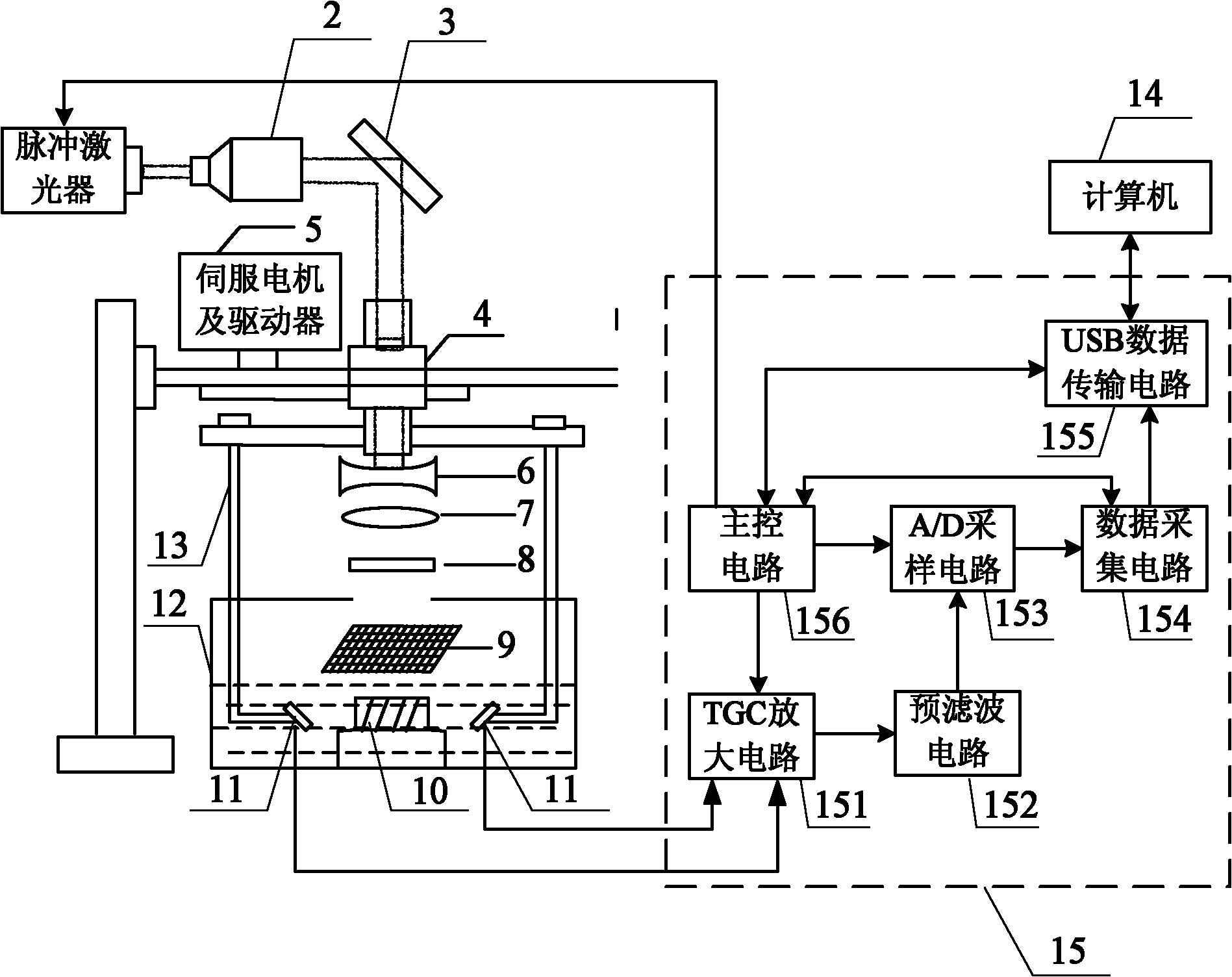
[0028] Specific implementation mode one: the following combination figure 1 Describe this embodiment. This embodiment is based on a compressed sensing single-array element multi-angle observation photoacoustic imaging device, which includes a pulsed laser 1, a pulsed laser processing device, a servo motor and a driver 5, an optical mask 9, and a single-array element ultrasonic detection device. Device 11, sample pool 12, support 13, computer 14 and signal acquisition circuit 15,
[0029] An optical mask 9 is set directly above the sample pool 12, the output end of the measurement matrix of the signal acquisition circuit 15 is connected to the input end of the optical mask 9, the beam control end of the signal acquisition circuit 15 is connected to the control end of the pulsed laser 1, and the pulse The pulsed laser light emitted by the laser 1 is processed by the pulsed laser processing device, then emitted to the surface of the optical mask 9, and irradiated in the sample ce...
specific Embodiment approach 2
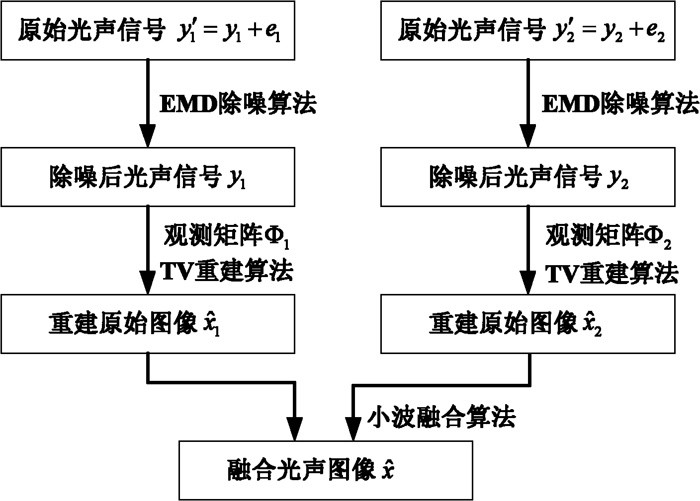
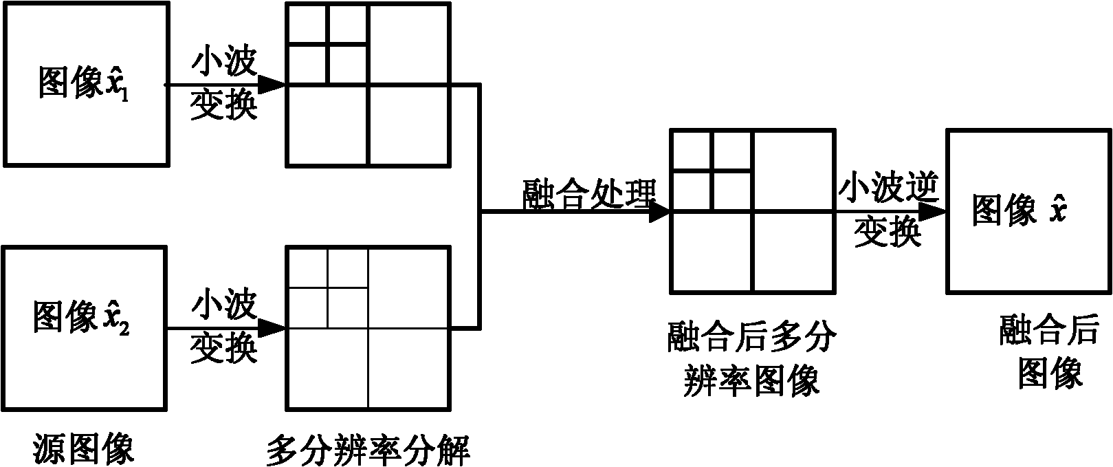
[0044] Specific implementation mode two: the following combination Figure 2 to Figure 7 To illustrate this embodiment, based on the method of compressive sensing-based multi-angle observation photoacoustic imaging device described in the first embodiment, the method includes the following steps:
[0045] Step 1. Place the biological tissue 10 to be tested in the center of the sample pool 12. The FPGA built in the main control circuit 156 emits a pulse signal to trigger the pulsed laser 1. At the same time, the optical mask 9 is controlled to generate a random matrix, and the pulsed laser 1 generates laser pulses. , after the laser pulse is processed by the pulse laser processing device, it is irradiated onto the biological tissue 10 to be measured through the optical mask 9 to generate a photoacoustic signal;
[0046] Step 2, the servo motor and the driver 5 adjust the observation angles of the two single-array element ultrasonic probes 11 through the sleeve 4 and the bracket...
PUM
 Abstract
Description
Claims
Application Information
 - R&D
- Intellectual Property
- Life Sciences
- Materials
- Tech Scout
- Unparalleled Data Quality
- Higher Quality Content
- 60% Fewer Hallucinations
Browse by: Latest US Patents, China's latest patents, Technical Efficacy Thesaurus, Application Domain, Technology Topic, Popular Technical Reports.
© 2025 PatSnap. All rights reserved.Legal|Privacy policy|Modern Slavery Act Transparency Statement|Sitemap|About US| Contact US: help@patsnap.com


