Positioning device and method for rail traffic vehicle

A technology for rail transit vehicles and rail vehicles, which is applied in the direction of measuring devices, optical devices, instruments, etc., can solve the problem that the meter-level positioning accuracy cannot meet the demand, and achieve the advantages of matching positioning, high sampling frequency, and improving positioning accuracy Effect

Active Publication Date: 2011-05-25
BEIJING JIAOTONG UNIV
View PDF3 Cites 37 Cited by
  • Summary
  • Abstract
  • Description
  • Claims
  • Application Information

AI Technical Summary

Problems solved by technology

For such applications, such as tunnel body deformation analysis, slope deformation analysis, trackside equipment deformation analysis, etc., the meter-level positioning accuracy will not meet the demand

Method used


Image

  • Positioning device and method for rail traffic vehicle
  • Positioning device and method for rail traffic vehicle
  • Positioning device and method for rail traffic vehicle

Examples


Embodiment 1

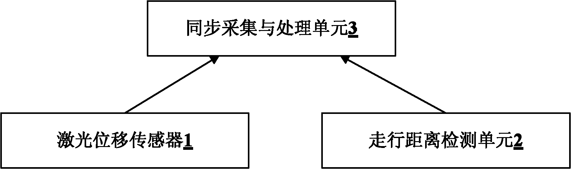
[0027] refer to figure 1 , figure 1 It is a structural schematic diagram of an embodiment of a positioning device for rail transit vehicles in the present invention, including: a laser displacement sensor 1 , a rail vehicle travel distance detection unit 2 and a synchronous acquisition and data processing unit 3 .

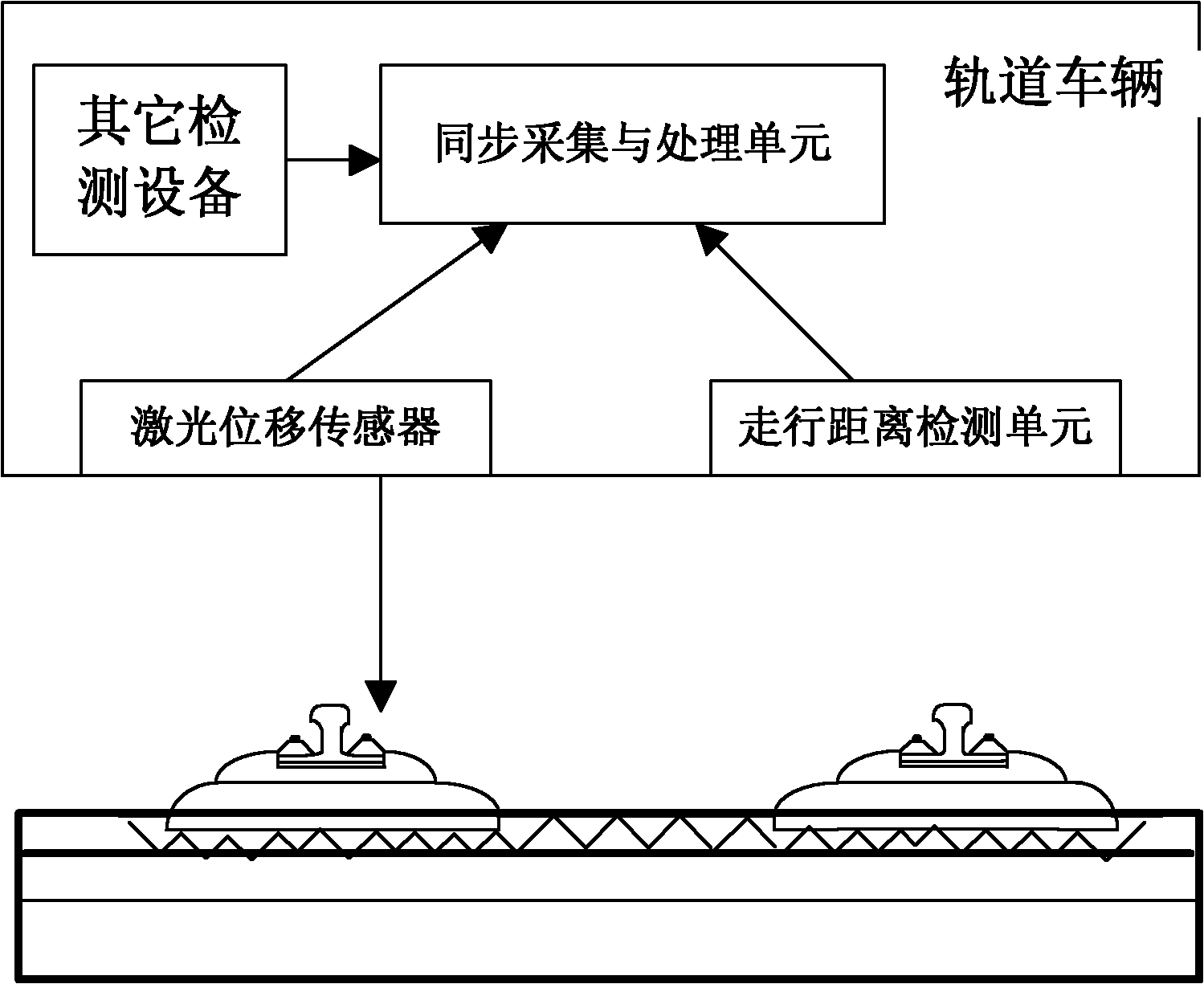
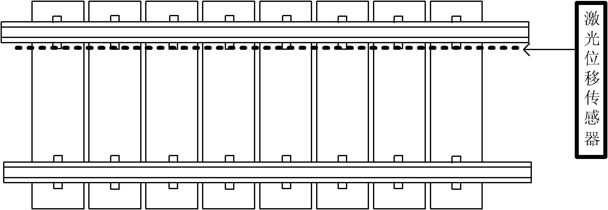
[0028] Among them, refer to figure 2 and image 3 As shown, the laser displacement sensor 1 is aligned near the inner fastener of the track, and the output of the laser displacement sensor is the distance between the installation position and the surface of the track.

[0029] The train travel distance detection unit 2 outputs the position change amount of the rail vehicle along the track direction. The train running distance detection unit 2 can be composed of a wheel shaft pulse sensor, which outputs several pulses every time the wheel rotates. Under the condition that the wheel diameter is known, the running distance can be obtained by calculating the number...

Embodiment 2

[0035] refer to Image 6 , this embodiment is a system for detecting deformation of a tunnel body using the positioning device described in the present invention. This system includes laser displacement sensor, axle pulse sensor, data synchronous acquisition circuit, data processing module and data processing software. It also includes other detection equipment, such as other sensors, including GPS receivers, tunnel section measurement sensors, vehicle attitude measurement sensors and cameras. The system is installed on rail vehicles or manually pushed rail cars, and the initial positioning of the system is obtained through GPS signals. During the detection process, the data synchronous acquisition circuit synchronously acquires the output of each sensor, and then transmits it to the data processing module for real-time storage. The judgment of tunnel body deformation can be performed in real time or offline. (1) First, the data processing module aligns the data collected i...


PUM


Abstract

The invention relates to a positioning device and a positioning method for a rail traffic vehicle. The positioning device comprises a laser displacement sensor, a rail vehicle traveling distance detection unit and a synchronous acquisition and data processing unit, wherein the laser displacement sensor and the rail vehicle traveling distance detection unit are respectively connected with the synchronous acquisition and data processing unit. In the method, the distance between the vehicle and a rail is detected by using an on-vehicle laser displacement sensor; the traveling distance of the vehicle is obtained by the output of a wheel shaft pulse sensor or two on-vehicle laser displacement sensors; and finally, rail characteristic data is acquired by using an on-vehicle data acquisition processing module. The acquired rail characteristic data is matched with the historical data of rail characteristics to realize high-precision absolute or relative positioning.

Description

technical field [0001] The invention relates to train operation control and infrastructure dynamic detection of rail traffic, in particular to a positioning device and method for rail traffic vehicles. Background technique [0002] Train positioning technology is one of the key technologies of rail transit train operation control, and it is the basis for ensuring driving safety and shortening the running interval between trains. The existing train positioning technology mainly uses the odometer based on wheel axle counting, together with other auxiliary means, such as query transponder, Doppler radar, track circuit, inter-track induction loop, wireless spread spectrum positioning, satellite positioning system, line map Matching, line image matching, turnout position matching, catenary limiter position matching and other technologies can automatically correct the cumulative error of the odometer caused by factors such as wheel idling, slipping, serpentine, and wear. Based on...

Claims


Application Information

Patent Timeline
Patent Type & Authority Applications(China)
IPC IPC(8): B61L25/02G01B11/02G01B11/14
Inventor 朱力强郭保青余祖俊史红梅许西宁
Owner BEIJING JIAOTONG UNIV
Why Eureka
Try Eureka