
System and method for performing transistor-level static performance analysis using cell-level static analysis tools

a technology of static analysis and transistor level, applied in the field of transistor-level static analysis spa methods, can solve the problems of less robust tool suite available for sta at the transistor level than at the cell-level, impracticality, and less widely available cell-level timing tools, etc., to achieve excellent incremental accuracy, excellent absolute accuracy, and extremely fast runtime

Inactive Publication Date: 2011-01-04
RPX CORP +1
View PDF10 Cites 2 Cited by
  • Summary
  • Abstract
  • Description
  • Claims
  • Application Information

AI Technical Summary

Benefits of technology

[0005]For the static timing analysis (STA) embodiment, the gate-to-drain and source-to-drain delays for each transistor-equivalent cell are obtained using a circuit simulator and stored, as cell information, in the STA engine cell library. For a Synopsis STA system, the library in which cell information is stored is referred to as Synopsys Liberty (.lib). The cell-level netlist and characterized cell library files are used in an STA flow for worst-case (or best-case) timing analysis. Using this flow, transistor-level timing analysis can be performed with good absolute accuracy and excellent incremental accuracy, with extremely fast runtimes, and without the need to access a transistor-level STA engine.

Problems solved by technology

Unfortunately, for large circuits this technique becomes impractical due to the huge number simulation runs, each with a different input vector, which would have to be performed to gain a good confidence level that a worst case input vector had been identified.
Because it is more unusual to design circuits at the transistor level, the tool suite available for performing STA at the transistor level is less robust than at the cell-level.
Although at least one transistor-level STA tool does exist, it is less widely available than the cell-level timing tools.

Method used


Image

  • System and method for performing transistor-level static performance analysis using cell-level static analysis tools
  • System and method for performing transistor-level static performance analysis using cell-level static analysis tools
  • System and method for performing transistor-level static performance analysis using cell-level static analysis tools

Examples


Embodiment Construction

of Proposed Method

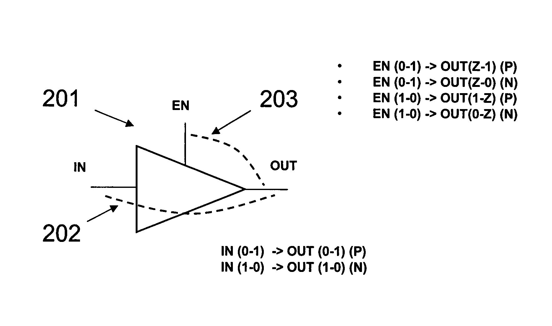
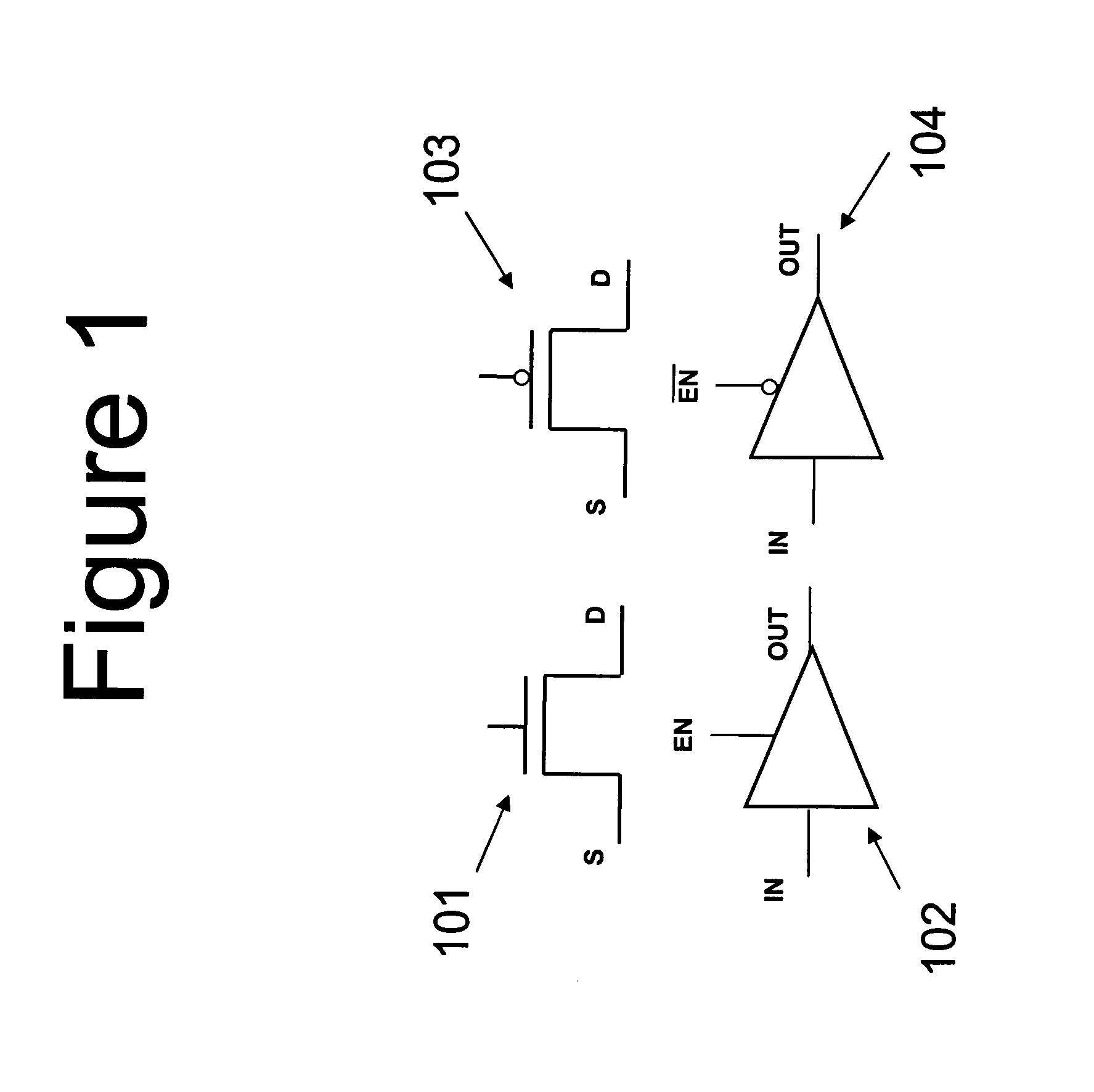
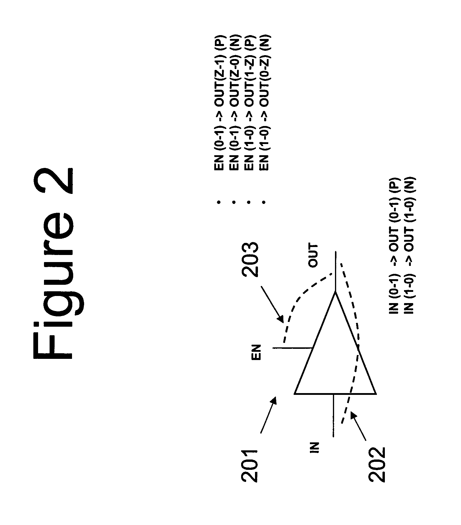
[0033]Referring to FIG. 6, a cell level model for a two-FET inverter 600 has a worst case rise time when the buffer 601, which models a PMOS FET, is enabled. Likewise, the worst case fall time for inverter 600 occurs when the buffer 602, which models an NMOS FET, is enabled. The gate->drain delay of the PMOS FET modeled by buffer 601 (arc 603) is used for rise time analysis. Similarly, the gate->drain delay of the NMOS FET modeled by buffer 602 (arc 604) is used for fall time analysis.

[0034]Referring to FIG. 7, a cell level model representing a NAND gate 700 has a worst case rise time when one of the PMOS FETs modeled by buffers 701 and 702“turns on.” The slower of the two arcs 705 is used by the STA engine. The case for fall time analysis is more complicated, and is handled as discussed in the text accompanying FIG. 3. The figure shows the arcs 706 and 707 only for the case where AT(A2)+DG2+DS1>AT(A1)+DG1.

[0035]Referring to FIG. 8, for a multi-stage AND gate 800 t...


PUM


Abstract

A method of using a static performance analyzer that accepts as input a cell-level netlist, to perform static performance analysis on a circuit represented by a transistor level netlist. The method begins with converting said transistor-level netlist to a cell-level netlist by modeling individual transistors with a cell model. Then, a static performance analyzer is used to perform a static performance analysis of said cell-level netlist. Among performance characteristics that may be analyzed are timing (static timing analysis) and leakage power. The method described may also be used for statistical static timing and power analysis.

Description

CROSS-REFERENCE TO RELATED APPLICATIONS[0001]This application claims the benefit of provisional application Ser. No. 60 / 906,443, filed Mar. 12, 2007.BACKGROUND[0002]The present invention relates to transistor-level static performance analysis SPA methods. SPA is a method of bounding the performance of an integrated circuit (IC) design, prior to actually creating the IC in silicon. This is done by postulating worst case or best case performance at every signal flow juncture, for worst case or best case bounds, respectively. One particularly important type of SPA is static timing analysis (STA), in which timing performance is bounded. In STA, both best and worst case bounds are critical for insuring that there will be no timing mismatches, internal and external to the chip. Another technique, known as dynamic timing analysis, is the process of simulating circuit performance for a particular input set or vector. Unfortunately, for large circuits this technique becomes impractical due t...

Claims


Application Information

Patent Timeline
Patent Type & Authority Patents(United States)
IPC IPC(8): G06F17/50
CPCG06F17/5031G06F17/5036G06F17/504G06F30/3323G06F30/3312G06F30/367
Inventor KAHNG, ANDREW B.GUPTA, PUNEETSHAH, SAUMIL
Owner RPX CORP
Learn More