
Method for removing cyanide, thiocyanate, COD and arsenic in waste liquid

A technology of thiocyanate and cyanide, which is applied in the field of thiocyanate, COD and arsenic, to remove cyanide in waste liquid, and can solve problems such as inability to treat cyanide in depth

Active Publication Date: 2011-05-25
CHANGCHUN GOLD RES INST +1
View PDF7 Cites 19 Cited by
  • Summary
  • Abstract
  • Description
  • Claims
  • Application Information

AI Technical Summary

Problems solved by technology

Within the range of pH value controlled by sections, there is no need to strictly require the concentration of ozone generation and mass flow rate, which can solve the problem that a single process cannot deeply treat cyanide, thiocyanate, COD, and arsenic in waste liquid, and reduce the process equipment. Cost and operational complexity, reducing environmental pollution

Method used


Image

  • Method for removing cyanide, thiocyanate, COD and arsenic in waste liquid
  • Method for removing cyanide, thiocyanate, COD and arsenic in waste liquid
  • Method for removing cyanide, thiocyanate, COD and arsenic in waste liquid

Examples


Embodiment 1

[0115] The composition of a gold concentrate cyanidation leaching residue leaching waste liquid is shown in Table 3

[0116] Table 3 Composition of a gold concentrate cyanidation leaching residue leaching waste liquid

[0117] Unit: mg / L, pH dimensionless

[0118]

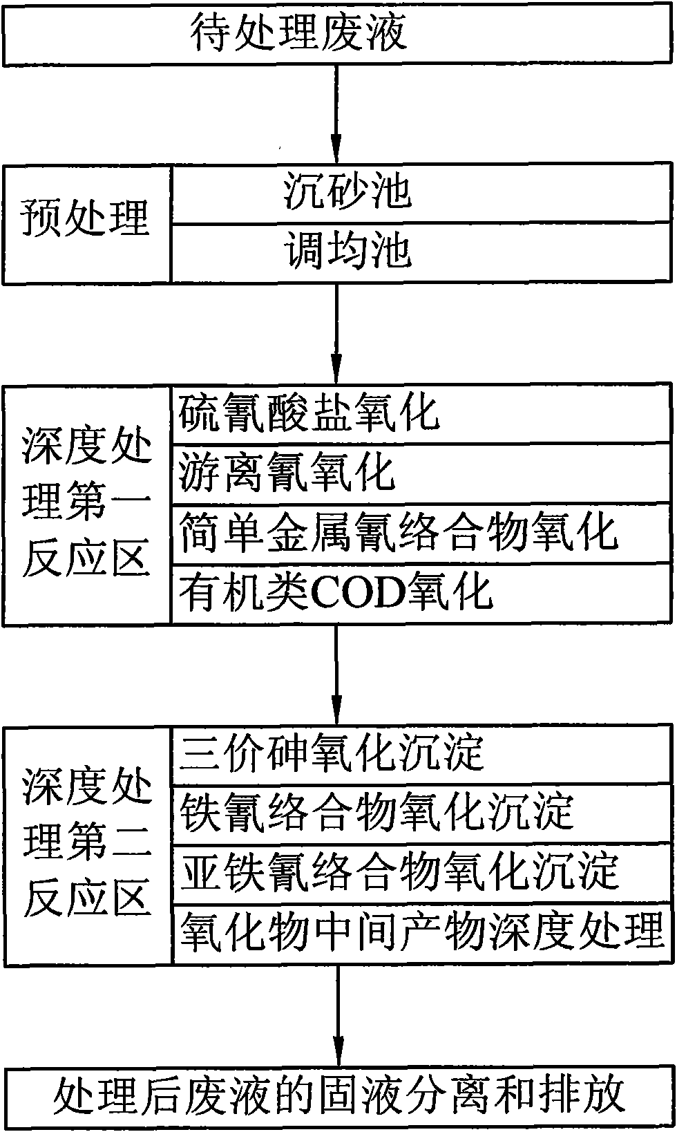
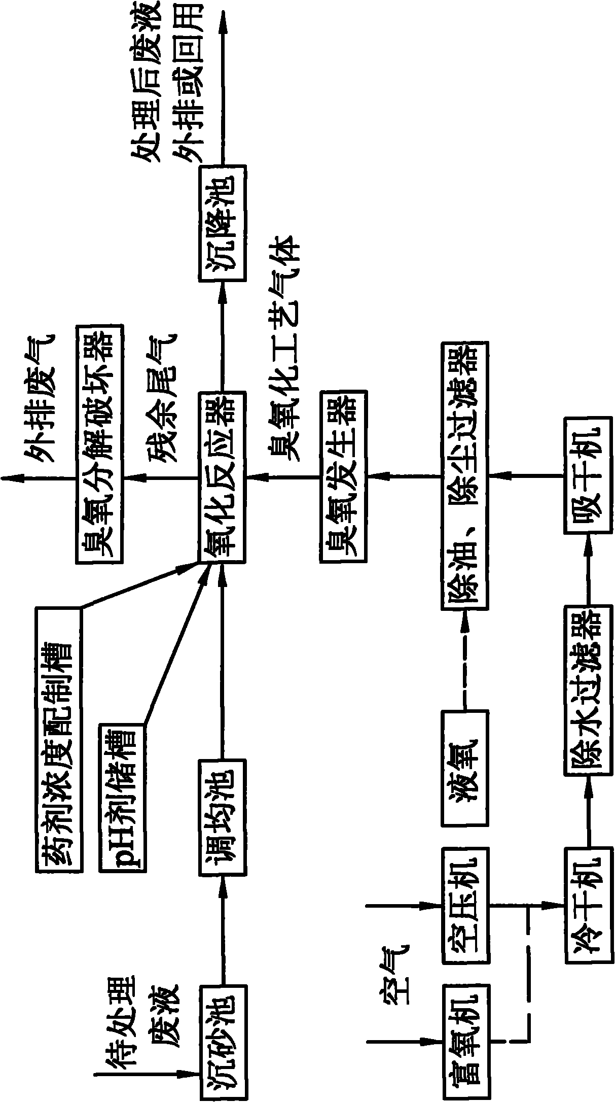
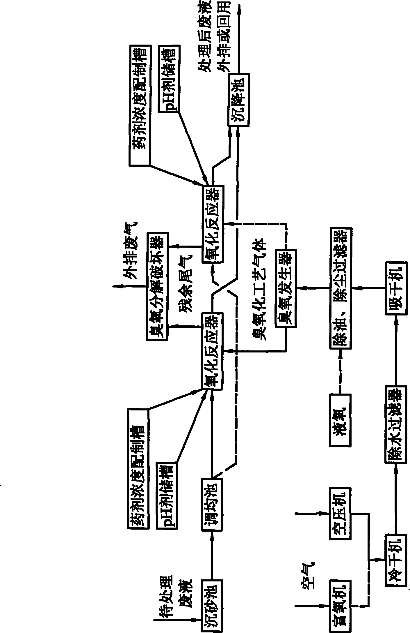
[0119] From the composition of the above wastewater quality, it can be seen that the main pollutants of wastewater are CN T 、SCN - , As, COD, where SCN - The proportion of COD is relatively high, so the reaction process is mainly for the analysis and determination of the above four pollutants. see figure 1 and figure 2 Shown:

[0120] (1) Pretreatment section: After the waste liquid to be treated passes through the grit chamber to settle the solid suspended matter in the waste liquid, it enters the equalization tank.

[0121](2) Continuous treatment: Turn on the upper liquid pump to extract the liquid to be treated from the equalizing tank at the maximum flow rate, and pour it into the oxidation reactor ...

Embodiment 2

[0130] The composition of a gold ore cyanidation leaching cycle barren solution, see Table 5

[0131] Table 5 Summary of composition of barren liquid sampling and analysis in cyanidation leaching system of a factory

[0132] Unit: mg / L, pH dimensionless

[0133] serial number

CN T

SCN -

Cu

Pb

Fe

Zn

As

COD

pH

1

343.82

1591.25

0.0167

micro

0.0003

micro

-

1703.14

12

2

315.85

1320.34

0.0172

micro

0.0003

micro

-

1540.92

12

3

341.75

1569.43

0.0166

micro

0.0003

micro

-

1681.10

12

4

310.68

1317.83

0.0167

micro

0.0003

micro

-

1529.82

12

5

311.54

1318.24

0.0152

micro

0.0003

micro

-

1549.97

12

6

310.68

1320.97

0.01...


PUM


Abstract

The invention discloses a method for removing cyanide, thiocyanate, COD and arsenic in waste liquid, comprising the following steps: the cyanide, the thiocyanate, the COD and the arsenic in the waste liquid are deeply treated by utilizing ozonized gas, a mode with continuous treatment and direct discharge can be adopted, also a mode with batch treatment and intermittent discharge can be adopted, and the implementation process of the method is easy to control; in the range of the pH value with sectioned control, the generation concentration and mass velocity of ozone do not need to be required strictly, the problem that single technology can not treat the cyanide, the thiocyanate, the COD and the arsenic in the waste liquid deeply can be solved, the cost and the operation complexity of technological equipment are reduced, and the environmental pollution is reduced; solid suspensions (SS) in the treated waste liquid is removed by settlement, and clear liquor is directly discharged outwards or returned to the upstream technology for repeated use; the contents of pollutants in the treated waste liquid are stable, the total content of the cyanide is less than 0.2mg / L(waste water); the content of the thiocyanate is less than 5mg / L(waste water); the total content of the COD is less than 30mg / L; the total content of the arsenic is less than 0.5mg / L(waste water), and no secondary pollutants are generated in the reaction process.

Description

technical field [0001] The invention relates to the field of water treatment and environmental protection, in particular to a method for removing cyanide, thiocyanate, COD and arsenic in waste liquid. technical background [0002] In industrial production, the cyanide method has always been an important means of gold and silver wet extraction, so a certain amount of waste liquid containing cyanide and cyanide derivatives must be discharged during the production process, which contains various types of waste liquid depending on the nature of the ore Free cyanide with different concentrations and simple metal cyanide complexes, refractory metal cyanide complexes, and cyanide derivatives such as cyanate, thiocyanate, and cyanogen chloride, are suitable for refractory gold mines. The cyanidation waste liquid after biological pre-oxidation, autoclave oxidation, and oxidative roasting contains highly toxic water-soluble trivalent arsenic ions, and the environmental protection prob...

Claims


Application Information

Patent Timeline
IPC IPC(8): C02F9/04C02F101/18C02F101/16
Inventor 李延吉李哲浩陈民友降向正
Owner CHANGCHUN GOLD RES INST
Learn More