Device for preventing elongated piston rod from bending deformation during medium and high frequency quenching

A technology for preventing bending deformation and high-frequency quenching, applied in the direction of quenching device, improving energy efficiency, improving process efficiency, etc. The performance is improved, the straightening process is omitted, and the effect of not easy to grind cracks

Inactive Publication Date: 2012-05-30
福建省龙岩液压集团有限公司
View PDF2 Cites 1 Cited by
  • Summary
  • Abstract
  • Description
  • Claims
  • Application Information

AI Technical Summary

Problems solved by technology

If the axis line of the workpiece after clamping is inconsistent with the axis line of the coil, it will cause the coil to touch the workpiece when moving axially, and the quenching thickness will be uneven, which will increase the difficulty of the subsequent grinding process
The medium-high frequency quenching machine tool is positioned by two tops. During the heating process, the workpiece heats up sharply, which will inevitably produce thermal expansion effect. Originally, a large extrusion force was generated when clamping, and the two ends cannot be elongated after heating and expansion. Severely extruding the workpiece will cause large bending deformation, which is absolutely not allowed for the piston rod of the hydraulic cylinder. It will seriously affect the sealing performance of the hydraulic cylinder, or directly strain the surface of the piston rod during movement. Make production enterprises and users suffer losses
The conventional treatment method is to straighten the rod after medium and high frequency quenching, which will complicate the processing technology and waste manpower and material resources, and the deformation may not be well eliminated

Method used


Image

  • Device for preventing elongated piston rod from bending deformation during medium and high frequency quenching
  • Device for preventing elongated piston rod from bending deformation during medium and high frequency quenching
  • Device for preventing elongated piston rod from bending deformation during medium and high frequency quenching

Examples


Embodiment Construction

[0015] The following embodiments will further illustrate the present invention in conjunction with the accompanying drawings.

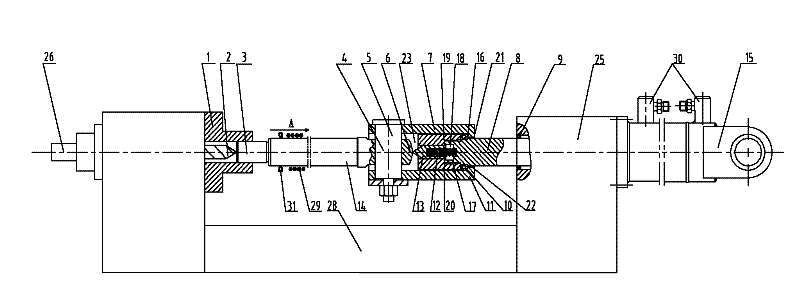
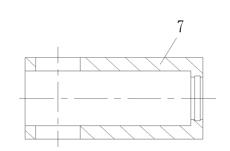
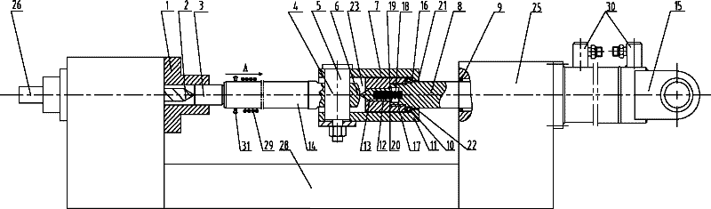
[0016] see figure 1 with 2 , the embodiment of the present invention is provided with machine tool 28, tailstock 25, insert body 7, axial thrust bearing 10, movable top 13, top lock nut 11, thrust spring 12, connecting bolt 4 and tension hydraulic cylinder 15; The insert body 7 is installed on the piston rod 8 of the stretching hydraulic cylinder 15, the leftward movement of the insert body 7 is limited at the right end of the axial thrust bearing 10, and the inner wall of the inner hole 23 of the insert body 7 and the axial thrust bearing 10 There is a gap between it and the top lock nut 11, the insert body 7 is connected with the quenched workpiece 14, the piston end 3 of the piston rod 8 is inserted into the three-jaw chuck 1 of the machine tool and offset against the top 2, and the piston rod 8 is also provided with There are connecting threads ...


PUM


Abstract

The invention discloses a device for preventing an elongated piston rod from bending deformation during medium and high frequency quenching, and relates to a metal part surface thermal treatment device. The device is provided with a plug body, an axial thrust bearing, a movable tip, a tip locking nut, a thrust spring, a connecting bolt and a tensile hydraulic cylinder, wherein the plug body is arranged on the piston rod of the tensile hydraulic cylinder; leftward movement of the plug body is limited at the right end of the axial thrust bearing; a gap is reserved between the inner wall of an inner hole of the plug body and the axial thrust bearing as well as the tip locking nut; the plug body is connected with a workpiece to be quenched; the piston end of the piston rod is clamped in a three-claw chuck of a machine tool and is pressed against a tip; the piston rod is provided with connecting threads and steps; the thrust spring is arranged in a counter bore which is formed at the frontend of the piston rod of the tensile hydraulic cylinder; the movable tip is pressed against the end part of the connecting bolt; the tensile hydraulic cylinder is fixed on a tail seat of the machine tool; and the center of an end face of the plug body is provided with a through hole in which a supporting ring is arranged. Through the device, the elongated piston rod can be prevented from bending deformation in the medium and high frequency quenching process.

Description

technical field [0001] The invention relates to a surface heat treatment device for metal parts, in particular to a device for preventing bending deformation of a slender piston rod during medium-high frequency quenching. Background technique [0002] Medium-frequency quenching is used for surface heat treatment of metal parts. The depth of the quenching layer is generally about 2-4mm. The advantage of this process is that it can harden the surface of the part and increase the wear resistance of the part, while the internal material of the part remains the original performance. The piston rod of the hydraulic cylinder in construction machinery often needs to extend and retract, and it also needs to withstand severe impacts from external loads, which is a huge challenge to the service life of the hydraulic cylinder. After medium and high frequency quenching, the surface wear resistance of the piston rod is greatly enhanced, and the mechanical properties are greatly improved,...

Claims


Application Information

Patent Timeline
Patent Type & Authority Patents(China)
IPC IPC(8): C21D1/62C21D1/10C21D9/00
CPCY02P10/25
Inventor 魏锦超吴榕唐雯沈顺良张文渭杜明星
Owner 福建省龙岩液压集团有限公司
Why Eureka
Try Eureka