Ultra-long distance distribution type optical fiber sensor and using method thereof

A technology of distributed optical fiber and sensing device, which is applied in the fields of vibration sensing, long-distance distributed optical fiber temperature, and distributed optical fiber sensing. Long-distance detection needs and other issues, to achieve the requirements of reducing the receiving sensitivity and dynamic range, the spatial resolution is not affected, and the effect of reducing loss

Inactive Publication Date: 2011-05-25
SHANGHAI BOOM FIBER SENSING TECH
View PDF0 Cites 11 Cited by
  • Summary
  • Abstract
  • Description
  • Claims
  • Application Information

AI Technical Summary

Problems solved by technology

[0003] In the distributed optical fiber sensing device, the scattered signal intensity decreases exponentially with the increase of the detection distance. In the case of not reducing the signal-to-noise ratio of the device, there are usually two methods, one is to increase the incident power of the light source, and the other is to increase the The sensitivity and dynamic range of the receiving circuit; but in fact, the incident power of the light source and the sensitivity of the receiving power and the dynamic range are limited, which are far from meeting the needs of ultra-long-distance detection

Method used


Image

  • Ultra-long distance distribution type optical fiber sensor and using method thereof
  • Ultra-long distance distribution type optical fiber sensor and using method thereof
  • Ultra-long distance distribution type optical fiber sensor and using method thereof

Examples


Embodiment 1

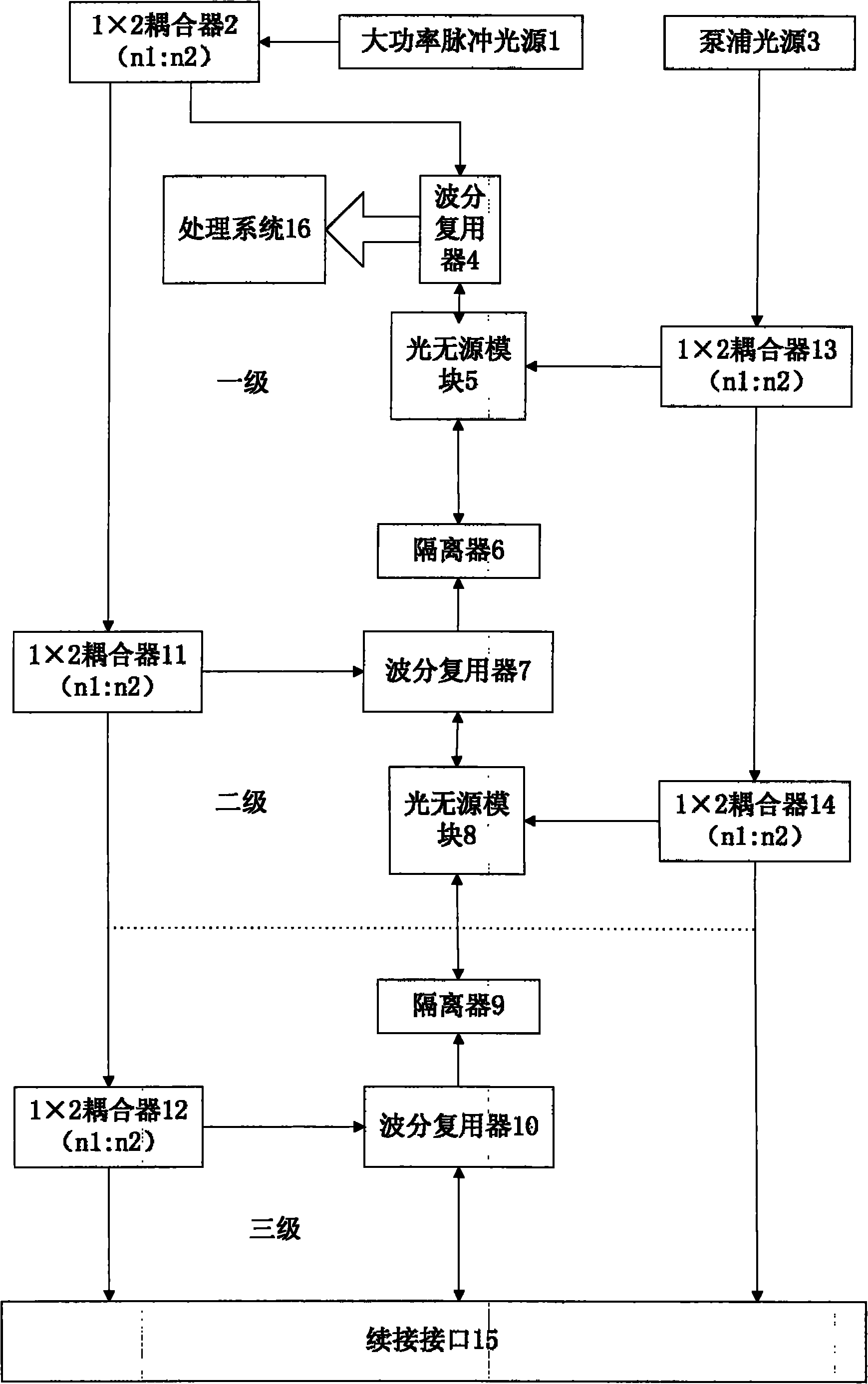
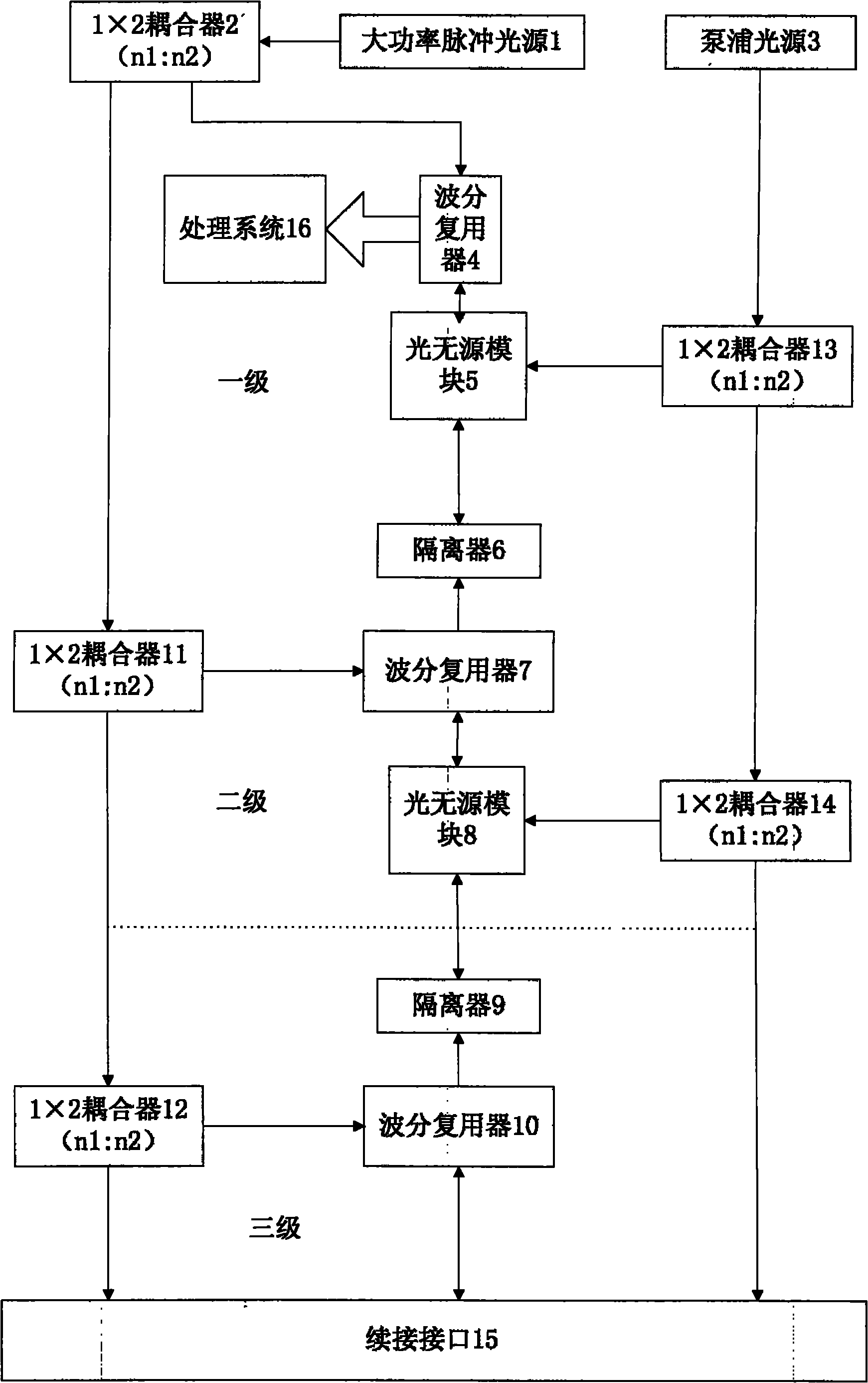
[0020] Embodiment 1: as figure 1 , the pulse light sent by the high-power pulse light source 1 is divided into two parts through the fiber coupler 2, one part directly enters the first-stage wavelength division multiplexer 4, and the other part enters the second-stage fiber coupler 11 through the transmission fiber; The multiplexer 4 is connected to the optical passive amplifier module 5, the pump light emitted by the pump light source 3 is split by the fiber coupler 13, part of it enters the optical passive amplifier module 5 to provide energy for it, and the other part enters the second stage through the transmission fiber The fiber coupler 14, the EDFA passive module 5 is connected to the isolator 6; the second-stage fiber couplers 11 and 14 respectively input the pulse light and the pump light into the second-stage wavelength division multiplexer 7 and the optical passive amplification module as required 8. The remaining light is transmitted to the next-level fiber coupler...

Embodiment 2

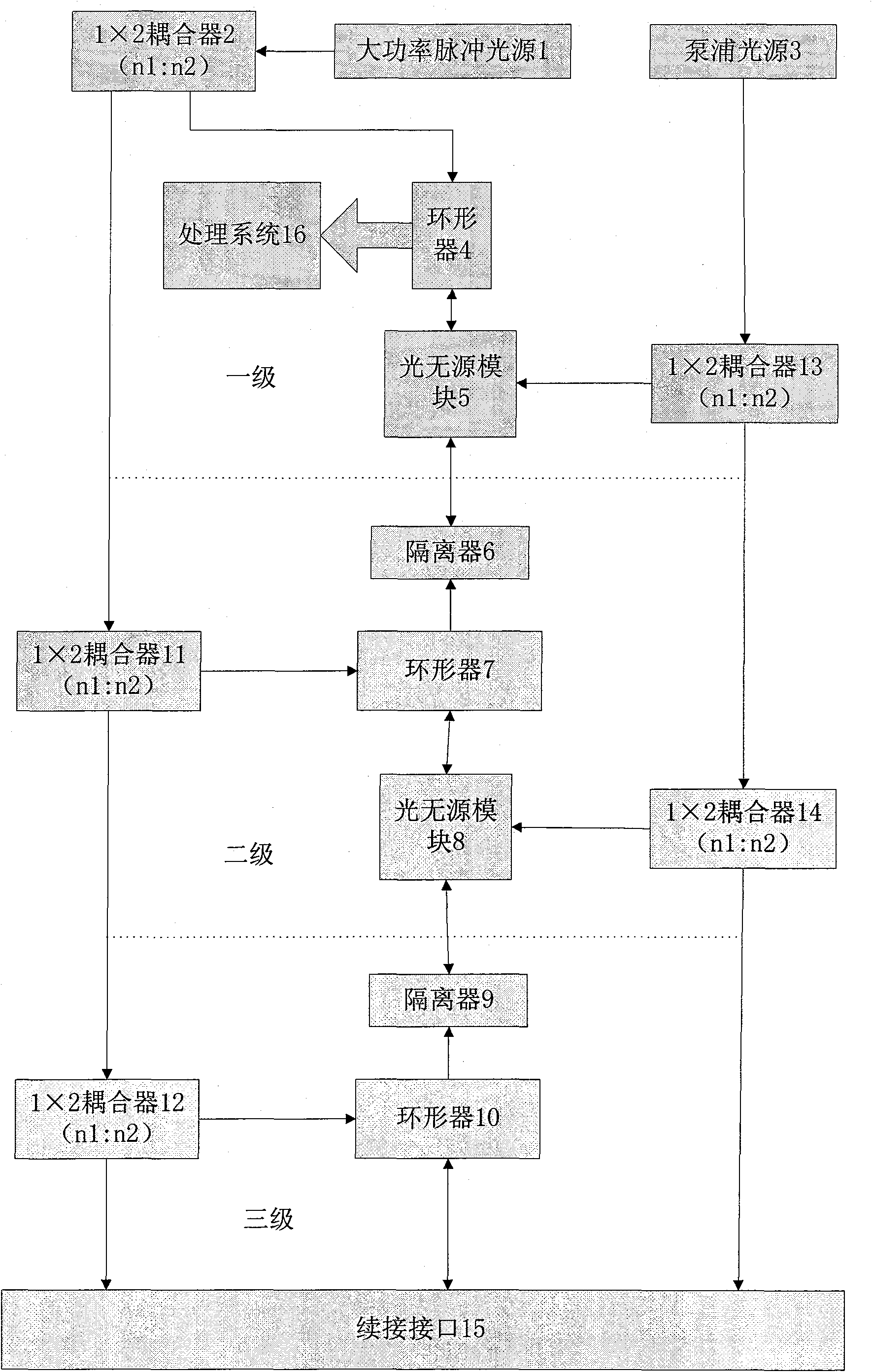
[0023] Embodiment 2: as figure 2 The pulse light emitted by the high-power pulse light source 1 is divided into two parts through the fiber coupler 2, one part directly enters the circulator 4 of the first stage, and the other part enters the fiber coupler 11 of the second stage through the transmission fiber; The source amplifier module 5 is connected, the pump light emitted by the pump light source 3 is split by the fiber coupler 13, a part of it enters the optical passive amplifier module 5 to provide energy for it, and the other part enters the second-stage fiber coupler 14 through the transmission fiber, and the EDFA The passive module 5 is connected to the isolator 6; the second-stage fiber couplers 11 and 14 respectively input pulsed light and pump light into the second-stage circulator 7 and the optical passive amplification module 8 as required, and the rest of the light is transmitted to the The next-stage optical fiber coupler, the connection port 15 can be connect...


PUM


Abstract

The invention discloses an ultra-long distance distribution type optical fiber sensor and a method for measuring temperature and vibration signals. The ultra-long distance distribution type optical fiber sensor adopts a multi-stage relay amplifier, and a high-power pulse light source enters a detecting optical fiber stage by stage through proportional allocation of a plurality of optical fiber couplers and transmission of transmission fibers, and re-amplifies the pulse of the detecting light at a specified length, thereby improving the signal to noise ratio of the system in terms of 'source', being capable of avoiding non-linear scattering caused by overrun light which enters a detecting optical cable directly on one hand, and being capable of reducing higher energy loss caused by continuous light transmission on the other hand. The ultra-long distance distribution type optical fiber sensor adopts the staged design, thereby greatly reducing the requirement on receiving sensitive and dynamic range of a receiving circuit. In addition, the ultra-long distance distribution type optical fiber sensor adopts the expandable design, thereby being capable of conveniently realizing short-distance detection, long-distance detection and ultra-long distance detection in sequence.

Description

technical field [0001] The invention relates to the technical field of distributed optical fiber sensing, in particular to the technical field of long-distance distributed optical fiber temperature and vibration sensing. Background technique [0002] The distributed optical fiber sensing device is based on the principle of light backscattering. When the laser pulse is transmitted in the optical fiber, Raman scattering (Stokes, anti-Stokes), Rayleigh scattering and Brillouin scattering will be continuously generated in the optical fiber. Scattering and other scattered light, part of which will be transmitted to the "source" in the opposite direction, we call this part of the scattered light "backscattered light". The scattered light signal is relatively weak and requires a high-sensitivity photodetector and an amplifier circuit to receive it. [0003] In the distributed optical fiber sensing device, the scattered signal intensity decreases exponentially with the increase of ...

Claims


Application Information

Patent Timeline
Patent Type & Authority Applications(China)
IPC IPC(8): G01D5/353G01K11/32G01H9/00G01K11/324
Inventor 郭兆坤皋魏席刚仝芳轩周正仙
Owner SHANGHAI BOOM FIBER SENSING TECH
Why Eureka
Try Eureka