Exact impedance designing method for circuit layout

A technology of circuit layout and design method, applied in computing, electrical digital data processing, special data processing applications, etc., can solve the problem of misjudgment of current value calculation of electronic components, etc., and achieve the effect of increasing production cost

Inactive Publication Date: 2011-05-25
INVENTEC CORP
View PDF0 Cites 2 Cited by
  • Summary
  • Abstract
  • Description
  • Claims
  • Application Information

AI Technical Summary

Problems solved by technology

[0004] The purpose of the present invention is to solve the technical problem of misjudgment of the current value calculation of electronic components during the layout of the existing circuit board

Method used


Image

  • Exact impedance designing method for circuit layout
  • Exact impedance designing method for circuit layout
  • Exact impedance designing method for circuit layout

Examples


Embodiment Construction

[0013] The detailed structure of the present invention and its connections are now described in conjunction with the following figures.

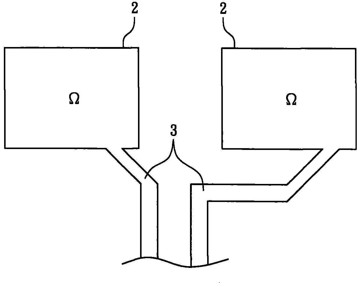
[0014] see Figure 4 As shown, it is a schematic diagram of separating the soldering pad of the electronic component from the signal line of the electronic component to make it open and separate, wherein the precise impedance design method of the circuit layout of the present invention is on a printed circuit board (not shown in the figure), The welding pad of the electronic component is separated from the signal line of the electronic component by breaking the circuit to form a non-electrical connection between the welding pad and the signal line, and any structure that makes the welding pad and the signal line disconnected belongs to the present invention scope of protection.

[0015] The above-mentioned pads and signal lines are both made of copper foil. After the two are disconnected and separated, the independent pads 4 and the indepen...


PUM


Abstract

The invention relates to an exact impedance designing method for circuit layout. In the invention, a pad of an electronic component and a signal wire of the electronic component are disconnected and separated so as to form non-electrical connection between the pad and the signal wire, but because when the electronic component is welded, a pin can be simultaneously and electrically connected to the pad and the signal wire to ensure that the resistance of the pad is not added to a detection point, thus the current signal measurement can be more exact.

Description

technical field [0001] The invention relates to a precise impedance design method for circuit layout. Background technique [0002] The progress of the electronics industry has resulted in the birth of many exquisite electronic products. To have exquisite electronic products, the layout design of the circuit board is very important. How to use the limited space to accommodate all electronic components and pull all the signal lines Good and normal operation, repeatedly test the wisdom of circuit board layout, and at a more detailed level, it is necessary to accurately calculate the characteristics of each electronic component (driving voltage, current and impedance value), in order to design electronic products that are not prone to failure . [0003] In some power integrated circuits (Power IC), it is necessary to obtain the current value of a signal line to cooperate with subsequent power control, please refer to figure 1 As shown, the power integrated circuit measures th...

Claims


Application Information

Patent Timeline
IPC IPC(8): G06F17/50
Inventor 施博元陈建诚
Owner INVENTEC CORP
Why Eureka
Try Eureka