Integrated regenerative fuel cell structure

A fuel cell, integrated technology, applied in the field of integrated proton exchange membrane renewable fuel cell structure, can solve the problems of complicated URFC cell structure design, unstable cell performance, cumbersome assembly process, etc., and achieves novel design and increased size The effect of simple reaction interface and assembly process

Inactive Publication Date: 2011-05-25
SHANGHAI INST OF SPACE POWER SOURCES
View PDF5 Cites 13 Cited by
  • Summary
  • Abstract
  • Description
  • Claims
  • Application Information

AI Technical Summary

Problems solved by technology

At present, the problems of integrated renewable fuel cells are: 1) The structural design of URFC cells is too complicated and the assembly process is cumbersome
2) When URFC works in water electrolysis mode, the oxygen electrode produces new ecological oxygen that is highly corrosive to the membrane electrode and flow field plate, resulting in poor FC / WE cycle life of URFC and unstable battery performance

Method used


Image

  • Integrated regenerative fuel cell structure
  • Integrated regenerative fuel cell structure
  • Integrated regenerative fuel cell structure

Examples


Embodiment Construction

[0035]Preferred embodiments of the present invention will be described below in conjunction with the accompanying drawings.

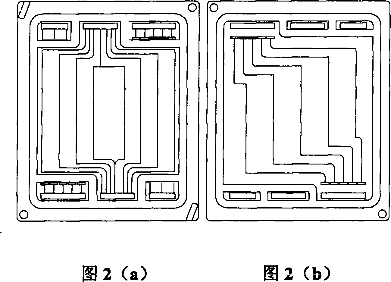
[0036] Such as figure 1 As shown, in the assembly structure of the integrated regenerative fuel cell provided by the preferred embodiment of the present invention, the anode insulation buffer plate A2, the anode conductive plate A3, the front special plate A4, the anode flow field assembly (water / oxygen double-sided flow field plate A5, plane limit metal ring A6, plane thin porous metal plate A7), double-effect membrane electrode assembly M1, cathode flow field assembly (plane thin porous metal plate B7, plane limit metal ring B6, hydrogen single-sided flow field plate B5 ), the rear special water plate B4, the cathode conductive plate B3 and the cathode insulating buffer plate B2 are sequentially stacked to form a battery stack;

[0037] Front-end plate A1 and rear-end plate B1 are respectively installed at both ends of the battery stack; the outer ed...


PUM


Abstract

The invention discloses an integrated regenerative fuel cell structure. In the cell structure, an anode insulating cushion plate [A2], an anode conducting plate [A3], a front special plate [A4], an anode flow field component, a double-effect membrane electrode component [M1], a cathode flow field component, a rear special water plate [B4], a cathode conducting plate [B3] and a cathode insulating cushion plate [B2] are stacked in turn to form a cell stack; two ends of the cell stack are provided with a front end plate [A1] and a rear end plate [B1]; and outer edges of the front end plate [A1] and the rear end plate [B1] are larger than those of other parts of the cell stack, areas of the front end plate [A1] and the rear end plate [B1] beyond the cell stack are provided with four edge holes at equal intervals, and screws are arranged in the edge holes to lock the cell stack. The integrated regenerative fuel cell has fuel cell and water electrolysis (WE) difunctional characteristic, can independently serve as a fuel cell and water electrolyzer, also can independently generate electricity or oxyhydrogen gas, and meets the requirement of a fixed fuel cell or transportation, including transportation tools and hydrogen refueling stations.

Description

technical field [0001] The invention relates to the field of regenerative fuel cells, in particular to an integrated proton exchange membrane regenerative fuel cell structure. Background technique [0002] Regenerative Fuel Cell (RFC for short), developed on the basis of hydrogen-oxygen fuel cell, is a new type of hydrogen energy power device that combines hydrogen-oxygen fuel cell technology with water electrolysis technology. Its working principle is: [0003] Positive electrode: 2H 2 O→O 2 +4H + +4e (Formula 1) [0004] Negative electrode: 4H + +4e→2H 2 (Formula 2) [0005] The total reaction of electrolysis: electric energy +2H 2 O→2H 2 +O 2 (Formula 3) [0006] Positive electrode: 2H 2 O→O 2 +4H + +4e (Formula 4) [0007] Negative electrode: 4H + +4e→2H 2 (Formula 5) [0008] Total power generation reaction: 2H 2 +O 2 →2H 2 O+electric energy (Equation 6) [0009] The water electrolyzer produc...

Claims


Application Information

Patent Timeline
Patent Type & Authority Applications(China)
IPC IPC(8): H01M8/18H01M8/10H01M8/02H01M4/88H01M8/0258H01M8/1004
CPCY02E60/521Y02E60/528Y02E60/50
Inventor 张新荣张伟王涛刘向童莉
Owner SHANGHAI INST OF SPACE POWER SOURCES
Why Eureka
Try Eureka