Assembly structure of motor

An assembly structure and motor technology, applied in electromechanical devices, manufacturing motor generators, electrical components, etc., can solve problems such as complicated installation methods, achieve the effects of reducing vibration, reducing length and space, and avoiding instant shock

Active Publication Date: 2012-11-21
H S MASCH CO LTD
View PDF0 Cites 4 Cited by
  • Summary
  • Abstract
  • Description
  • Claims
  • Application Information

AI Technical Summary

Problems solved by technology

The above-mentioned existing industrial sewing machine needs an additional indirect transmission through the toothed belt in the transmission mode in which the motor spindle drives the needle bar shaft and the main shaft to rotate. The installation method is complicated, and has its disadvantages in use, installation and transmission efficiency

Method used


Image

  • Assembly structure of motor
  • Assembly structure of motor
  • Assembly structure of motor

Examples


Embodiment Construction

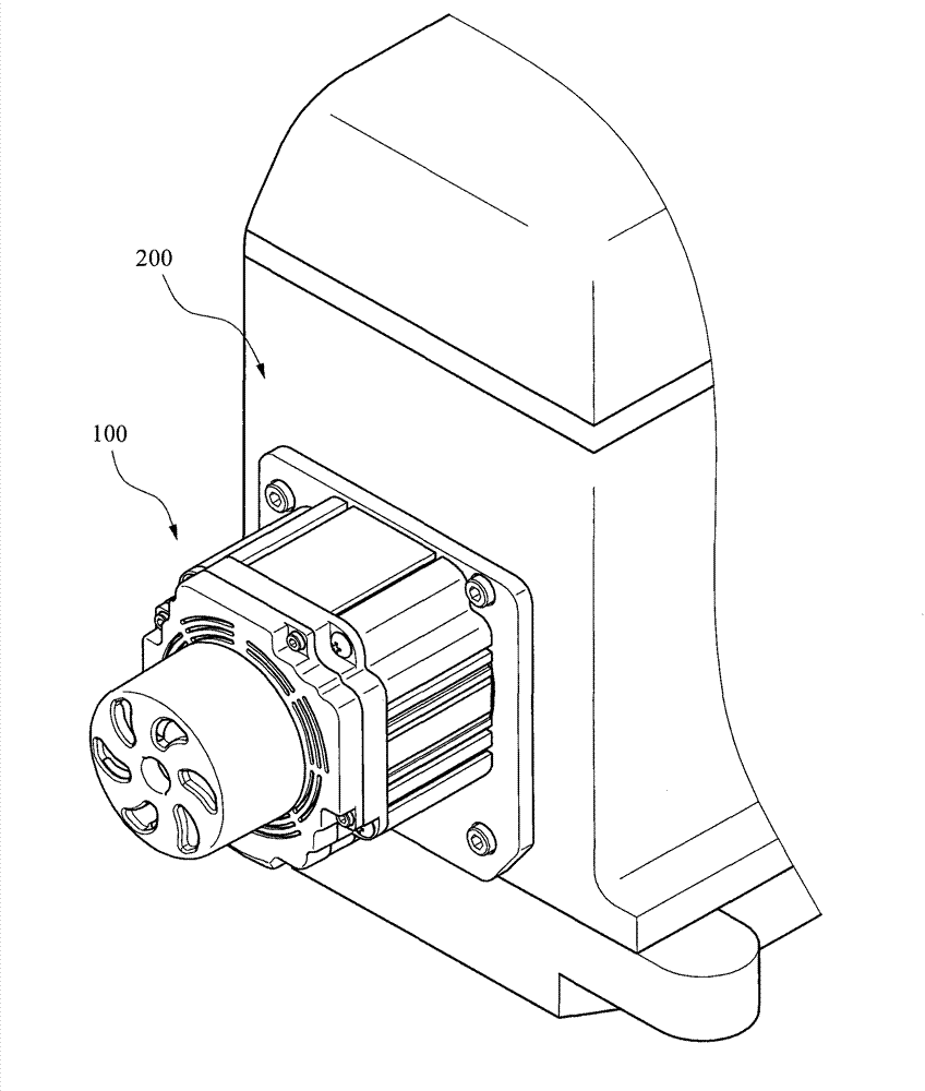
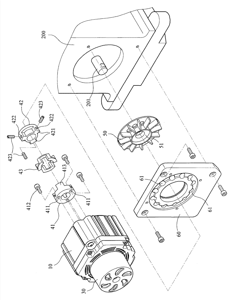
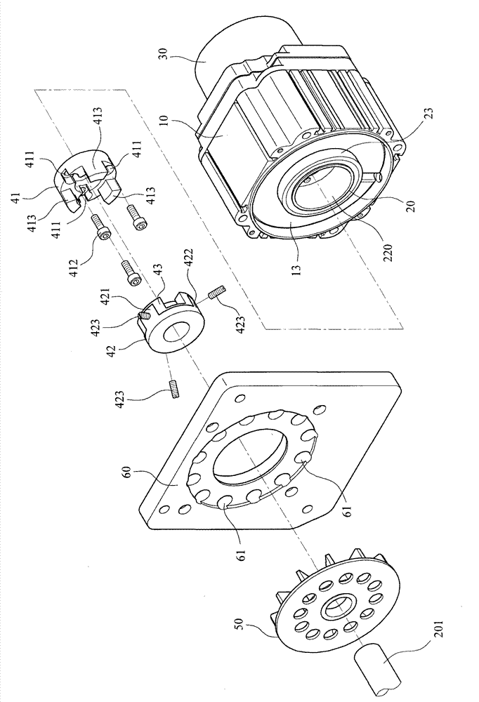
[0041] see Figure 1 to Figure 3 , is a perspective view, an exploded schematic diagram and an exploded schematic diagram in another direction of the first embodiment of the present invention. A motor 100 is directly assembled on the side of a machine base 200, and a mandrel 201 protrudes from the side of the machine base 200, and is mounted on the body 10 of the motor 100. There is a drive shaft 20 inside, and a stator and a rotor (not shown) are arranged between the drive shaft 20 and the body 10 .

[0042] Same reference Figure 4 , Figure 5 As shown in , one end of the drive shaft 20 is a small-diameter portion 21 long enough to pass through the body 10 of the motor 100. The small-diameter portion 21 passes through the part of the motor 100 to provide a handwheel 30. The selective threading device is fixed on the body of the motor 100. 10; while the other end of the drive shaft 20 expands to form a large-diameter portion 22, the large-diameter portion 22 is recessed wit...


PUM


Abstract

The invention discloses an assembly structure of a motor, which can directly assemble the motor on the side of an engine base. The motor is provided with a driving shaft, wherein a large-diameter part is arranged on a first end of the driving shaft; a small-diameter part is arranged on a second end of the driving shaft; a first accommodating space of a coaxial core is convexly formed in the large-diameter part and is used for fixedly arranging a first transmission part; and a second transmission part is fixedly arranged on a mandrel on the side of the engine base. The driving shaft of the motor, the first transmission part, the mandrel of the engine base and the second transmission part on the mandrel are radially and coaxially assembled in the large-diameter part of the driving shaft through the mutual corresponding coupling transmission of the second transmission part on the mandrel and the first transmission part on the driving shaft, so that the motor directly drives the mandrel of the engine base.

Description

field of invention [0001] The invention relates to an assembly structure between a motor and a machine base, in particular to an assembly structure of a motor for achieving radial coaxial drive. Background technique [0002] Existing industrial sewing machines, as shown in No. M256387 of Taiwan Patent Gazette of China, provide a coupling structure that can provide direct drive transmission for sewing and spinning machines, wherein the motor of the sewing machine is located at the upper end of the machine column, The mandrel of the motor is fixedly connected to one end of the shaft coupling. One end of the coupling is fixedly connected to the mandrel of the motor, and the other end is tightly connected to the front end of the needle bar shaft, so that the power of the motor can be passed through the mandrel. Output, and directly drive the needle bar shaft to run, and the peripheral wall of the coupling is integrally provided with ring teeth, so that the toothed belt is fitted...

Claims


Application Information

Patent Timeline
Patent Type & Authority Patents(China)
IPC IPC(8): H02K15/00H02K15/14
Inventor 李春长
Owner H S MASCH CO LTD
Why Eureka
Try Eureka