
Weir-pivoted decanter

A technology of plate weir decanter and flap, which is applied in chemical instruments and methods, biological water/sewage treatment, water/sludge/sewage treatment, etc., can solve the problems of high manufacturing and maintenance costs, poor decanting effect, Reduced maintenance costs, low operation and maintenance costs, and low sludge disturbance

Inactive Publication Date: 2011-06-01
CHENGDU UNIV
View PDF4 Cites 1 Cited by
  • Summary
  • Abstract
  • Description
  • Claims
  • Application Information

AI Technical Summary

Problems solved by technology

At present, common mechanical upgrade decanters, siphon decanters, buoy decanters, etc., mechanical decanters rely on mechanical transmission of power, and keep the decanting weir at a certain depth below the liquid surface when decanting water. After finishing, the decanting weir needs to be raised to the liquid level. The mechanical decanter has a complex structure and is expensive to manufacture and maintain; the siphon decanter uses the principle of siphon to suck out the supernatant liquid, so the airtightness of the decanter is required. High, when the decanting is stopped, the siphon needs to be destroyed, so the structure of the device is complicated, and the decanting flow is small; the buoy type decanter, by setting many holes on the wall of the drainage tube suspended on the buoy, makes the sewage treatment tank The supernatant liquid flows into the drainage channel, but when the supernatant liquid flows into the drainage channel through the holes on the wall of the cylinder, the water flow between two adjacent holes will be staggered and disordered, so the decanting effect is not good, because the hole diameter is small And the number of holes is limited, so the total decanting load is limited; although the above-mentioned decanters can meet the basic requirements of decanters, but they have different degrees of high manufacturing costs, relatively large power consumption during operation, maintenance Defects such as high cost, small weir load, poor decanting effect, etc.

Method used


Image

  • Weir-pivoted decanter
  • Weir-pivoted decanter
  • Weir-pivoted decanter

Examples


Embodiment 1

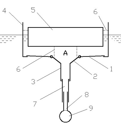
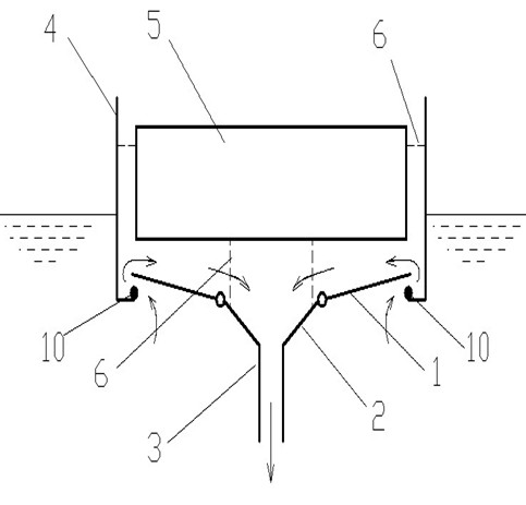
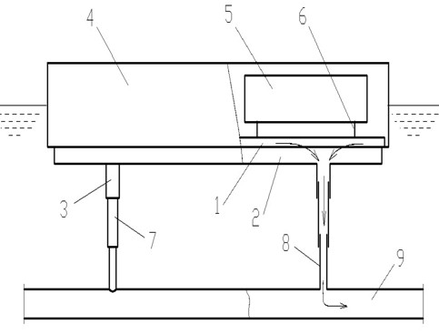
[0031] Example 1 as Figure 1 to Figure 4As shown, the flap weir decanter of the present invention includes an outer barrel box 4, the bottom of the outer barrel box 4 is connected with a diversion cone groove 2, and the lower end of the diversion cone groove 2 is connected with a drainage branch pipe 3, The drainage branch pipe 3 is set on the support pipe 8, and the support pipe 8 is connected to the drainage pipe 9. It is characterized in that: the outer barrel box 4 is connected with a buoyancy tank 5, and the diversion cone groove 2 The upper end of the tank is movably connected with a flap 1, and the flap 1 cooperates with the inner bottom of the outer barrel box 4 to form a decanting weir. The buoyant tank 5 is connected to the inner side wall of the outer tank 4 through the connecting rod 6 , and there is a gap between the buoyant tank 5 and the inner side wall of the outer tank 4 . The connecting pipe 7 is set inside the drainage branch pipe 3, and the connecting pip...


PUM


Abstract

The invention discloses a weir-pivoted decanter, which belongs to the field of sewage treatment equipment. The weir-pivoted decanter disclosed by the invention comprises an external barrel-shaped box (4), the bottom of the external barrel-shaped box (4) is connected with a conical diversion trench (2), the lower end of the conical diversion trench (2) is connected with a branch drain pipe (3), the branch drain pipe (3) is sleeved on a support pipe (8), the support pipe (8) is connected to a drain pipe (9), the inside of the external barrel-shaped box (4) is connected with a floating box (5), the upper end of the conical diversion trench (2) is movably connected with a turning plate (1), and the turning plate (1) is matched with the inner bottom of the external barrel-shaped box (4) so as to form a decanting weir crest. The weir-pivoted decanter disclosed by the invention has the advantages that the decanter is floated in the liquid in a reaction tank and automatically changes along with the liquid surface relying on the buoyancy of the water, therefore, the decanter is free from daily management; the components of the decanter have low possibility of being damaged, so the failure rate of the decanter is low, and the maintenance cost of the decanter is reduced; and laminar flow formed by water with gentle flow velocity has small disturbance on sludge, and the long weir crest enables the total flow to be large, therefore, the decanter has a good decanting effect and is suitable for promotion.

Description

technical field [0001] The invention relates to a sewage treatment device, in particular to a decanting device. Background technique [0002] In sewage treatment plants or some other sewage treatment projects, when using SBR process or similar processes, it is necessary to use a decanter to discharge the supernatant of the liquid in the reaction tank after the static sedimentation stage out of the tank. The basic requirements for the decanter are: in the aeration stage and the sedimentation stage, it should be able to prevent the sludge from entering the drainage channel of the decanter; in the decanting stage, it should be able to avoid disturbing the settled sludge at the bottom. The supernatant, excluding the surface scum, was drained. At present, common mechanical upgrade decanters, siphon decanters, buoy decanters, etc., mechanical decanters rely on mechanical transmission of power, and keep the decanting weir at a certain depth below the liquid surface when decanting ...

Claims


Application Information

Patent Timeline
Patent Type & Authority Applications(China)
IPC IPC(8): C02F3/12
CPCY02W10/10
Inventor 曾友为
Owner CHENGDU UNIV
Learn More