
Multi-motion mode planetary workpiece rest of vacuum coating machine

A vacuum coating machine, planetary technology, applied in the direction of vacuum evaporation coating, sputtering coating, ion implantation coating, etc., can solve the difficulty of arrangement and sealing performance guarantee, the complex structure of the multifunctional workpiece rack, and the inconvenience of operation for experimenters and other problems, to achieve the effect of simple and reasonable structure, simple structure, convenient and quick operation

Inactive Publication Date: 2011-06-01
NORTHEASTERN UNIV
View PDF3 Cites 12 Cited by
  • Summary
  • Abstract
  • Description
  • Claims
  • Application Information

AI Technical Summary

Problems solved by technology

This not only increases the cost of equipment manufacturing, but also brings inconvenience to the operation of experimenters.
A more advanced coating machine can use a multi-functional workpiece rack to achieve the above motion requirements, but this multi-functional workpiece rack is usually very complex in structure, and at least two independent drive systems are required to complete the above motion requirements
The use of two sets of drive systems not only doubles the equipment manufacturing cost, but also brings great difficulties to the peripheral equipment layout and sealing performance guarantee of the coating vacuum chamber

Method used


Image

  • Multi-motion mode planetary workpiece rest of vacuum coating machine
  • Multi-motion mode planetary workpiece rest of vacuum coating machine
  • Multi-motion mode planetary workpiece rest of vacuum coating machine

Examples


Embodiment Construction

[0024] The present invention will be further described below with reference to the accompanying drawings and embodiments.

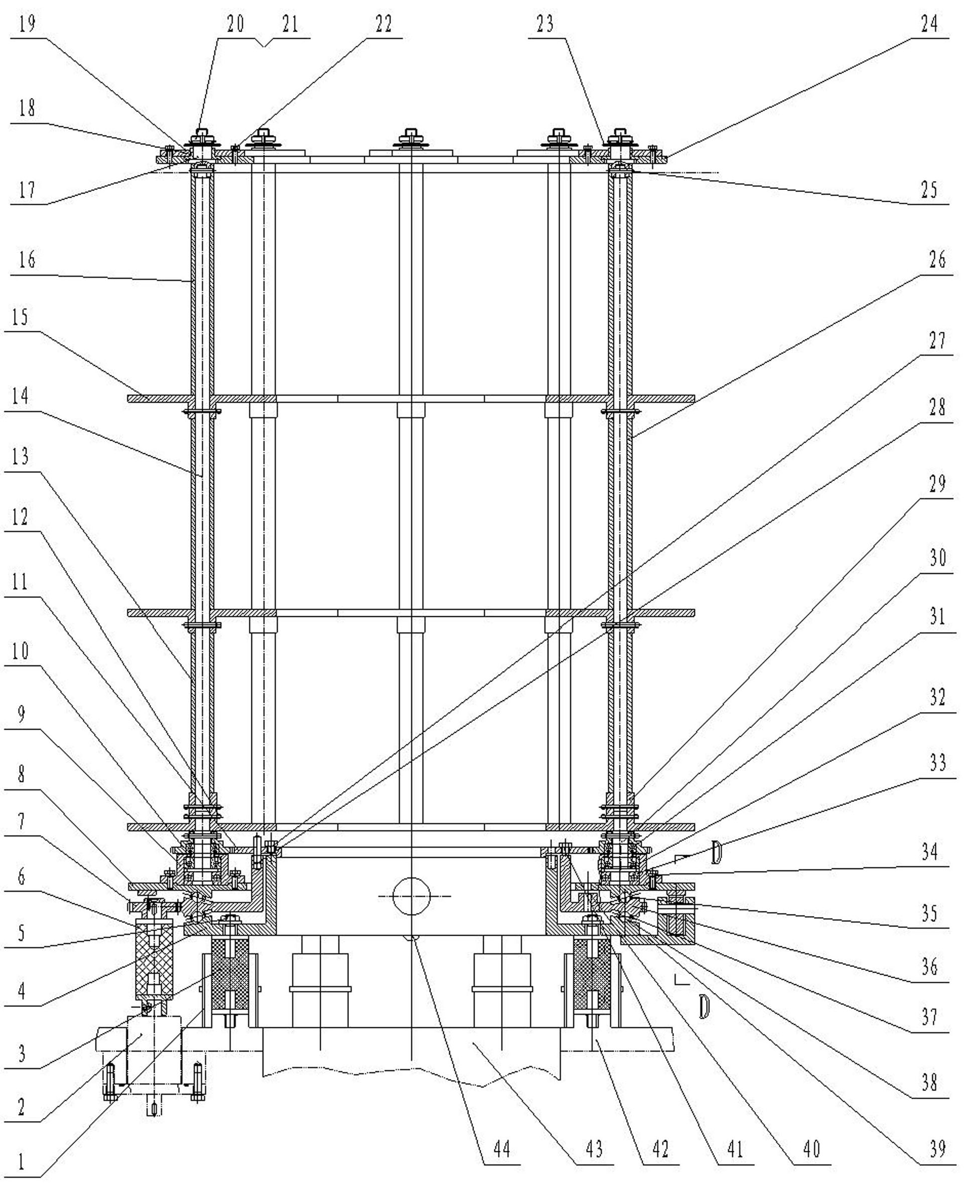
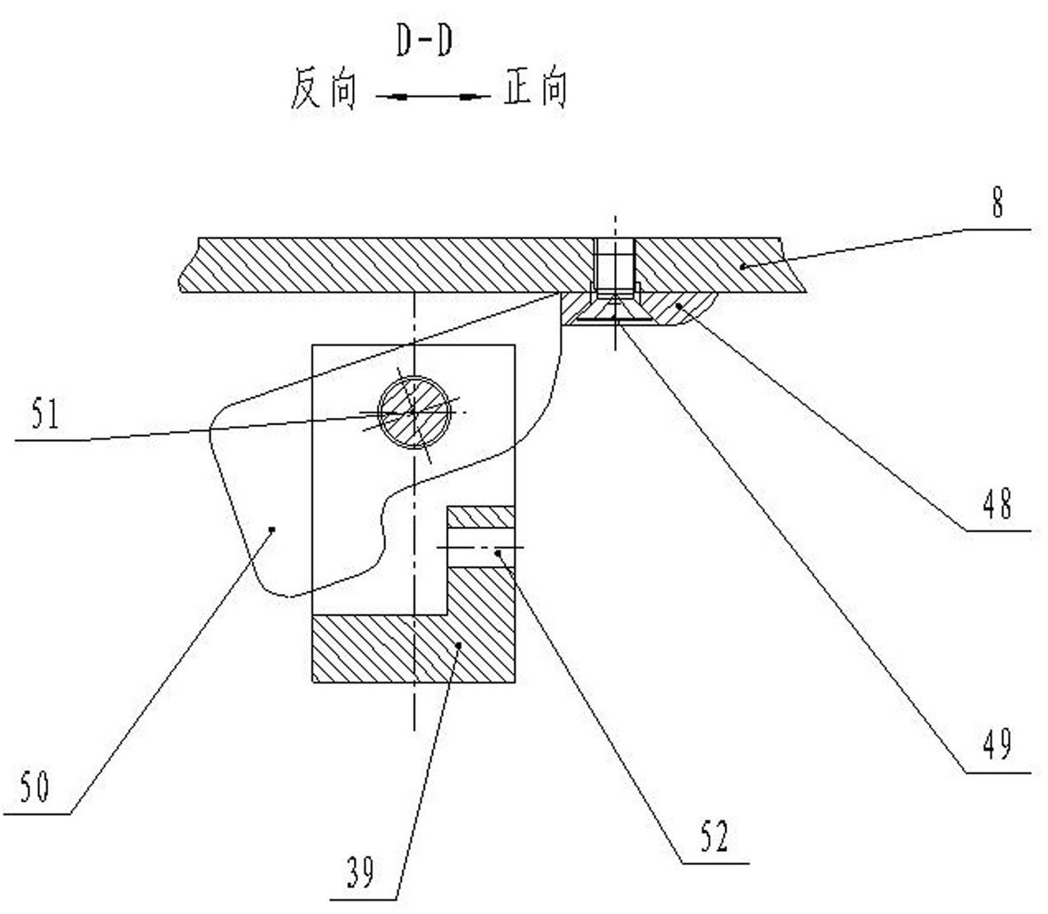
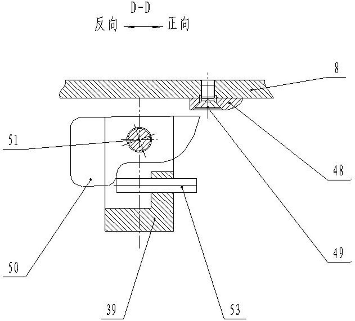
[0025] A planetary workpiece rack of a vacuum coating machine in a multi-movement mode of the present invention has a specific structure as follows: on the bottom plate 42 of the coating vacuum chamber, the lower support plate 4 of the workpiece rack is held up and fixed by a plurality of insulating support seats 3; Above the plate 4, the balls 38 constrained by the lower ball cage 37 hold up the middle support plate 36, and then the balls constrained by the upper ball cage 35 support the upper support plate 8. The ball slides between the three layers of support plates are: Inclined surface; the insulating support base 3 is arranged on the annular circumference of the vacuum chamber bottom plate 42, so that the vacuum chamber exhaust port 43 is arranged in the center of the vacuum chamber bottom plate 42; such as figure 1 As shown, the upper support plate...


PUM


Abstract

The invention discloses a multi-motion mode planetary workpiece rest of a vacuum coating machine, which comprises an insulation support seat, a frame body with a planetary type structure, a drive mechanism, a large gear ring and a pinion arranged on a planetary carrier rod. The multi-motion mode planetary workpiece rest of the vacuum coating machine is characterized in that the center of the lower part of the frame body is provided with a large-caliber exhaust hole and an exhaust channel; an upper supporting plate layer, a middle supporting plate layer and a lower supporting plate layer are supported by adopting balls in an inclined ramp; a stopping mechanism is arranged between the upper supporting plate layer and the lower supporting plate layer; the upper, the middle and the lower supporting plate layers are connected with the large gear ring through pins, the pinion is connected with the planetary carrier rod through pins, the multiple connection combinations are realized through the inserting and the drawing of the pins; and by means of positive and negative rotations of a single drive wheel, multiple motion modes that the workpiece carrier integrally makes single revolution, each planetary carrier rod makes planetary revolution and rotation, a carrier rod makes the single rotation and the target position conversion before the target position is appointed, and the like are realized. The invention provides a simple, convenient and quick key part structure for a vacuum film plating technology, and is suitable for change demands on a laboratory and multiple varieties and small batches of film plating productions.

Description

technical field [0001] The invention relates to the technical field of vacuum coating, in particular to a planetary workpiece holder with multiple movement modes used in a vertical multi-target vacuum sputtering (or ion) coating machine. Background technique [0002] In modern science and technology and industrial production, vacuum coating technology is in a very important position. Especially vacuum sputtering coating and vacuum ion coating are the most widely used physical vapor deposition coating methods. [0003] The small vacuum coating machines used for research work in the laboratory and the small and medium-sized coating machines used for small batch and multi-variety coating production are often faced with changing the variety, quantity and coating process of the workpieces to be plated at any time according to the needs of different research and production. Therefore, the existing types of vacuum coating machines usually have multiple coating sources (sputtering ...

Claims


Application Information

Patent Timeline
Patent Type & Authority Applications(China)
IPC IPC(8): C23C14/50
Inventor 张世伟韩进韩永超
Owner NORTHEASTERN UNIV
Learn More