Method for setting overcurrent protection point for insulated gate bipolar transistor

A bipolar transistor, overcurrent protection point technology, applied in emergency protection circuit devices, electrical components, etc., can solve the problems of inaccurate overcurrent judgment, no consideration of junction temperature factors, etc. Protect the effect of fast action

Active Publication Date: 2015-04-29
CHINA EPRI SCIENCE & TECHNOLOGY CO LTD +2
View PDF3 Cites 0 Cited by
  • Summary
  • Abstract
  • Description
  • Claims
  • Application Information

AI Technical Summary

Problems solved by technology

[0007] Aiming at the shortcomings of the IGBT overcurrent protection method in the prior art that does not consider the junction temperature factor and is inaccurate in judging the overcurrent, the purpose of the present invention is to provide a simple circuit, faster protection action, and more reliable IGBT overcurrent protection The setting method of the point, the overcurrent protection point obtained by this method takes into account the influence of the change of the IGBT junction temperature on the voltage V between the collector and the emitter. ce The impact of over-current is more accurate, and the protection of IGBT over-current is more timely and reliable.

Method used


Image

  • Method for setting overcurrent protection point for insulated gate bipolar transistor
  • Method for setting overcurrent protection point for insulated gate bipolar transistor
  • Method for setting overcurrent protection point for insulated gate bipolar transistor

Examples


Embodiment 1

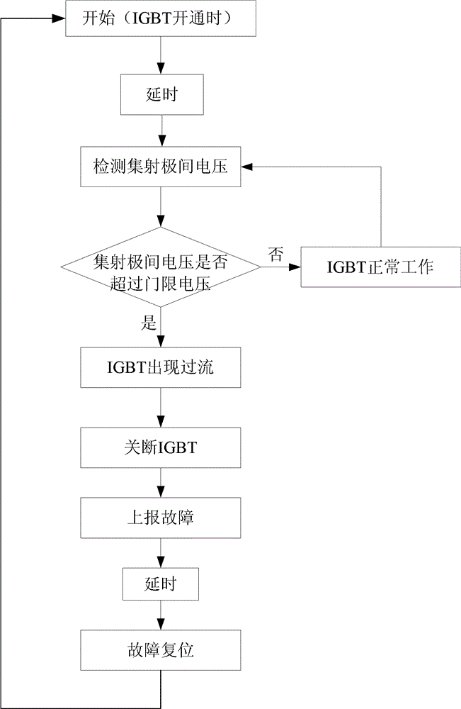
[0038] The setting method of the overcurrent protection point in the present invention is a setting method based on the driver, and the flow chart of the overcurrent detection and protection of the driver is shown in the attached figure 1 shown. A dynamic V on the driver ce After the voltage detection circuit is powered on, it starts to detect V ce Voltage, judge the size between the voltage Vce between the collector and the emitter and the threshold voltage, if the voltage Vce between the collector and the emitter is less than the threshold voltage, it means that the IGBT is in a normal working state; if the voltage Vce between the collector and the emitter exceeds the threshold Voltage, it can be judged that the IGBT is over-current, the driver reports back to the controller through the optical fiber, the controller sends a blocking signal, and the IGBT is turned off, so as to achieve the purpose of over-current protection.

Embodiment 2

[0040] In the present invention, according to the manufacturing process of the IGBT, it has been proved through many experiments that when the collector current I of the IGBT c When it is within 2 times the rated current, it is safe to turn off; when the collector current I of the IGBT c In the range of 2 times to 4 times the rated current, there is a risk of tube explosion when shutting off; when the collector current I of the IGBT c It is also safe to shut down when the rated current exceeds 4 times. Therefore, when setting the over-current protection, the shutdown current of the IGBT should be within 2 times the rated current at different junction temperatures to ensure the safety of the IGBT.

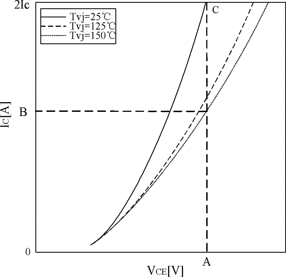
[0041] IGBT V at different junction temperatures ce Voltage vs. Collector Current I c The relationship curve is attached figure 2 As shown, it can be seen that at different junction temperatures, Vce with I c The correspondence is different, but V ce with I c The proportiona...

Embodiment 3

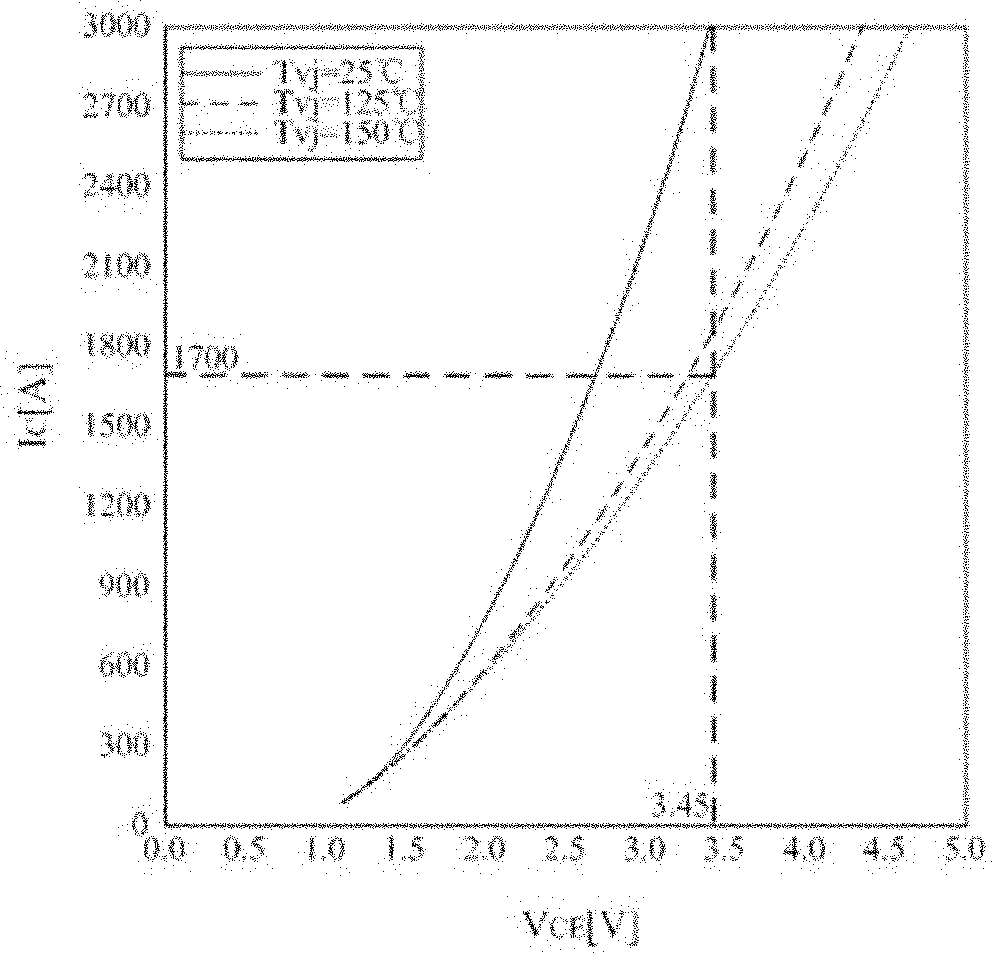
[0043] Taking two 3300V / 1500AIGBTs connected in parallel, the effective value of the rated working current of the device is 950A, and the maximum overload is 1.4 times as an example for analysis. The adopted driver is a master-slave driver, and the master-slave driver is connected through a parallel data line to respectively control the IGBTs used in parallel.

[0044] as attached image 3 As shown, the curve in the figure is the relationship curve between Vce and Ic of the IGBT device, the abscissa represents the conduction tube voltage drop Vce, and the ordinate represents the collector current Ic. The three curves in the figure represent the relationship between Vce and Ic when the junction temperature of the IGBT is 25°C, 125°C and 150°C respectively. It can be seen that as the current increases, the voltage drop of the conduction tube also gradually increases, and Vce It is basically proportional to Ic. The setting method of the overcurrent protection point is as follow...


PUM


Abstract

The invention provides a method for setting an overcurrent protection point for an insulated gate bipolar transistor, which comprises the step of setting an overcurrent protection point according to IGBT manufacturing process so as to control the cutoff current of IGBT within double rated current at different junction temperature and guarantee safe usage of an IGBT. The method for setting the overcurrent protection point takes the influence of junction temperature of IGBT on the overcurrent protection point into consideration, improves the detection accuracy, and protects the IGBT more effectively, timely and reliably.

Description

technical field [0001] The invention belongs to the field of power electronic devices, and in particular relates to a method for setting an overcurrent protection point of an insulated gate bipolar transistor. Background technique [0002] The insulated gate bipolar transistor (Insulated Gate Bipolar Transistor, IGBT) is a composite fully-controlled voltage-driven power As a semiconductor device, IGBT has the advantages of high input impedance of MOSFET and low turn-on voltage drop of GTR. The saturation voltage of GTR is low, the carrying current density is large, but the driving current is large; the driving power of MOSFET is small, the switching speed is fast, but the conduction voltage drop is large, and the current carrying density is small. IGBT combines the advantages of the above two devices, the driving power is small and the saturation voltage is low, its frequency characteristics are between MOSFET and power transistor, and it can work normally in the frequency ...

Claims


Application Information

Patent Timeline
Patent Type & Authority Patents(China)
IPC IPC(8): H02H7/20
Inventor 王轩邓占锋王柯韩天绪武守远俞旭峰邹俭其他发明人请求不公开姓名
Owner CHINA EPRI SCIENCE & TECHNOLOGY CO LTD
Why Eureka
Try Eureka