Anti-wire jumper sand-blasting device for multi-wire cutter

A kind of technology of multi-wire cutting machine and sandblasting device

Active Publication Date: 2012-06-20
ZHEJIANG JINGGONG SCI & TECH
View PDF0 Cites 0 Cited by
  • Summary
  • Abstract
  • Description
  • Claims
  • Application Information

AI Technical Summary

Problems solved by technology

The structure of the sandblasting device of the existing multi-wire cutting machine is relatively simple. Generally, only one end of the unilateral cutting steel wire is provided with a sandblasting device, and a linear spray mortar is used, and the distance between the steel wires on one side of the spray is Limited, such a way of blasting mortar will cause a lot of waste, and the utilization rate of mortar is low
In addition, at the outlet position closer to the conveying pipeline, the mortar flow rate is relatively large, and the formation of the mortar curtain is relatively continuous, while at the outlet position farther away from the conveying pipeline, the mortar flow rate is small, the flow is easy to stop, and the mortar blasting is uneven
In order to ensure that a continuous and complete mortar curtain can be formed, the flow rate of the mortar delivery pump must be increased, which will inevitably increase the power of the pump, which will increase energy consumption.
In order to save the overall flow, it is often adopted to reduce the diameter of the outlet of the sand blaster, resulting in a decrease in the anti-blocking ability of the sand blaster. If it is sensitive to impurities in the mortar, it is easy to cause flow interruption in some areas.
In addition, the currently commonly used sand blasters do not have the function of preventing steel wires from jumping when supplying mortar, which affects the smooth progress of steel wire cutting

Method used


Image

  • Anti-wire jumper sand-blasting device for multi-wire cutter
  • Anti-wire jumper sand-blasting device for multi-wire cutter
  • Anti-wire jumper sand-blasting device for multi-wire cutter

Examples


Embodiment Construction

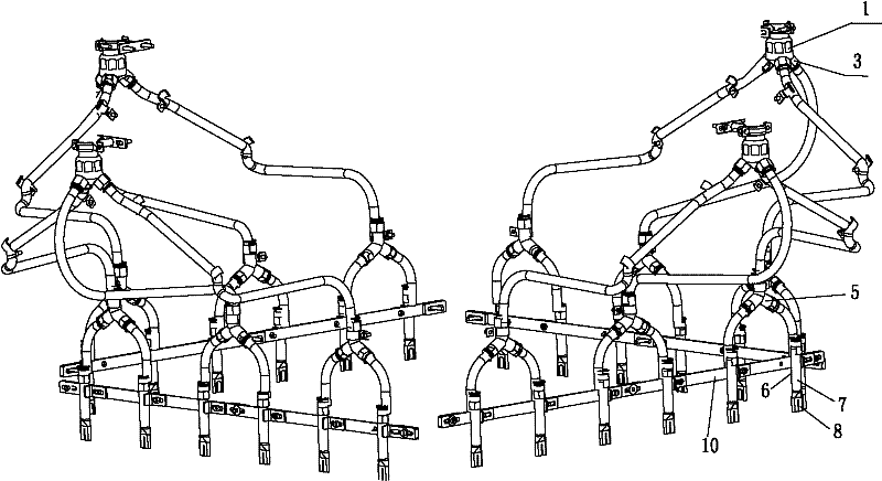
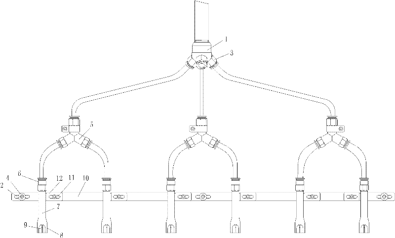
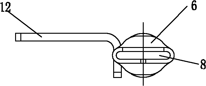
[0017] Such as figure 1 and figure 2 The shown anti-jumping sandblasting device for multi-wire cutting machine includes four sandblasting units arranged in a rectangle. The sandblasting unit includes a splitter head 1 and a plurality of sandblasters 6. Each outlet of the splitter head 1 is connected with The quick-plug connector 3 is also connected to the inlets of three tees 5 through flexible pipes, and the outlet of the three-way 5 is connected to the inlet of the sand blaster 6 through flexible pipes. One side of the sand blaster 6 forms a mounting plate 12 with a transverse waist groove 11, which is mounted on a horizontal plate 10 by fasteners. The horizontal plate 10 also has a lateral adjustment groove 2, which is fixed on the cutting head (omitted among the figures) by screws 4 . Such as image 3 and Figure 4 As shown, the sand blaster 6 includes a pipe body 7, the lower part of the pipe body 7 has an outwardly expanded nozzle 7, and the lower part of the pipe b...


PUM


Abstract

The invention relates to an anti-wire jumper sand-blasting device for a multi-wire cutter. The conventional sand-blasting device is non-uniform in sand blasting and is easy to block, and the normal operation is affected. The anti-wire jumper sand-blasting device comprises a plurality of sand-blasting units, and is characterized in that: each sand-blasting unit comprises a split-flow head and a plurality of sand-blasting machines; a plurality of outlet joints are formed on the lower part of the split-flow head, and each outlet joint is connected with an inlet of a tee joint by a hose; two outlets of the tee joint are respectively connected with an inlet of one sand-blasting machine; each sand-blasting machine comprises a tube body; a nozzle which expands outwards is formed on the lower part of the tube body; front and back anti-wire jumper grooves communicated with the nozzle are formed on the lower part of the tube body; and the tube body is arranged on a transverse plate. The anti-wire jumper sand-blasting device can improve the stability, uniformity and effectiveness of the sand blasting during multi-wire cutting, reduce wire break rate, improve cutting efficiency and cutting quality and prevent steel wires from hopping.

Description

technical field [0001] The invention relates to an auxiliary device for a multi-wire cutting machine that needs to use slurry abrasives for cutting, especially a sandblasting device that is used in conjunction with a multi-wire cutting machine for cutting polycrystalline silicon and single crystal ingots, and is used for conveying and distributing mortar while preventing jumping wires . Background technique [0002] Multi-wire cutting technology is a relatively advanced cutting technology in the world at present. A high-speed moving steel wire brings the cutting slurry abrasive into the cutting area for cutting. It is mainly used for cutting materials with high hardness and high brittleness. Because a steel wire is repeatedly wound into a cutting tool, and the steel wire is cut back and forth by going back and forth, so the utilization rate of the steel wire is high and the cutting efficiency is high. Steel wire needs to be ground by abrasives when cutting, so the attachmen...

Claims


Application Information

Patent Timeline
Patent Type & Authority Patents(China)
IPC IPC(8): B24C3/14B28D5/04
Inventor 王锋王明明徐建钢赵波
Owner ZHEJIANG JINGGONG SCI & TECH
Why Eureka
Try Eureka