Spliced stator iron core of tractor

A technology of stator iron core and machine stator, which is applied to synchronous machine parts, magnetic circuit shape/style/structure, magnetic circuit static parts, etc., can solve the problem of limiting the power output of the traction machine and increasing the circumference of copper wire , temperature rise and other problems, to achieve the effect of improving material utilization, reducing the length of copper wire, and reducing temperature rise

Active Publication Date: 2013-01-02
XJ SCHINDLER XUCHANG ELEVATOR +1
View PDF0 Cites 2 Cited by
  • Summary
  • Abstract
  • Description
  • Claims
  • Application Information

AI Technical Summary

Problems solved by technology

[0004] What is especially important is that since L2 is much larger than L1, the circumference of the copper wire coil becomes larger, and the resistance value of the stator coil 2' also increases accordingly, and the temperature rise caused by excessive resistance value during operation is too high, which greatly limits The power output of the tractor

Method used


Image

  • Spliced stator iron core of tractor
  • Spliced stator iron core of tractor
  • Spliced stator iron core of tractor

Examples


Embodiment Construction

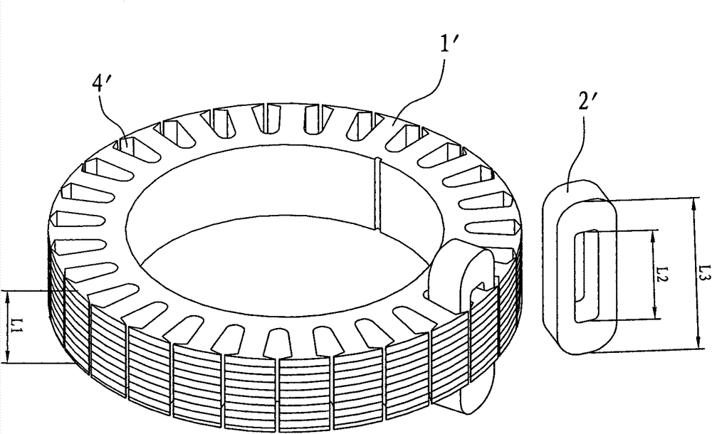
[0025] Such as Figure 5 --- Figure 7 As shown, a block-type traction machine stator core, the stator core 1 is composed of several separated stator blocks 2, and each separated stator block 2 is composed of multiple separated stator cores with the same outline 3 stacked and seen Figure 6 , a number of separate stator blocks 2 form a circular stator core with a certain thickness through a fixed structure (see Figure 11 ).

[0026] Each separated stator punching piece 3 is punched and formed by silicon steel sheet or other metal materials of standard thickness.

[0027] There is an interlocking structure between two adjacent separated stator punches 3, which is convenient for assembly and combination. Figure 9 : At A and B, the convex part of A is placed in the concave part of B to form as Figure 7 The interlocking structure shown is only one kind of embodiment.

[0028] The stator core 1 is composed of several separate stator blocks 2, such as Figure 10 Stator blo...


PUM


Abstract

The invention discloses a spliced stator iron core of a tractor. The stator iron core consists of a plurality of separated stator blocks, wherein each separated stator block is formed by laminating a plurality of blocks of separated stator stamped sheets with the same structure; a winding groove winding a stator coil is formed on each of the separated stator stamped sheets; and the plurality of separated stator blocks fix the plurality of separated stator blocks through pressing rings to form the annular stator iron core with a certain thickness. The invention provides a combined stator iron core. In the invention, the stator iron core of a lifter tractor is modified into a separated structure from an integrated structure, namely a tractor stator winding is divided into a plurality of separated stator iron cores, and the plurality of separated stator iron cores are combined into one through a reliable structure, so that the material utilization rate of the stator winding, the working performance of the tractor and the power output of the tractor are greatly improved.

Description

technical field [0001] The invention relates to a permanent magnet synchronous traction machine with an outer rotor structure, in particular to a stator core on the outer rotor permanent magnet synchronous traction machine. technical background [0002] Generally, permanent magnet synchronous traction machines are divided into inner rotor and outer rotor structures according to the relative positions of the stator and rotor. The inner rotor structure means that the rotor is inside the stator and is surrounded by the stator; the outer rotor structure is that the stator 1` is inside the rotor 5` and is surrounded by the rotor. See figure 1 and figure 2 . The traction machine and stator described in the present invention are limited to the outer rotor structure. [0003] The traditional outer rotor elevator traction machine stator consists of two parts, see image 3 : That is, the stator core 1' and the stator coil 2' wound on the stator core; the stator core 1' is compose...

Claims


Application Information

Patent Timeline
Patent Type & Authority Patents(China)
IPC IPC(8): H02K21/02H02K1/12
Inventor 刘成辉李明辉易小红刘金忠林万里王义彬
Owner XJ SCHINDLER XUCHANG ELEVATOR
Why Eureka
Try Eureka