
Force modulation mode-based dip-pen nanolithography method

A modulation mode, nanotechnology, applied in the fields of nanotechnology, nanotechnology, nanostructure manufacturing, etc., can solve the problems of occupied time, different, difficult to repeat the etching results, etc. The effect of etching results

Inactive Publication Date: 2011-06-15
SHANGHAI JIAO TONG UNIV
View PDF3 Cites 8 Cited by
  • Summary
  • Abstract
  • Description
  • Claims
  • Application Information

AI Technical Summary

Problems solved by technology

However, changing the parameters of SETPOINT, DRIVE AMPLITUDE, and LIFT HEIGHT can only qualitatively change the distance between the needle tip and the substrate, and the force between the needle tip and the substrate cannot be precisely controlled, which requires empirical speculation; and is affected by parameters such as the elastic coefficient of the needle tip , even if the parameter changes are the same, the changes caused by them will be different, and the etching results are difficult to repeat; in addition, these methods must perform repeated operations point by point when etching, which takes a lot of time

Method used


Image

  • Force modulation mode-based dip-pen nanolithography method
  • Force modulation mode-based dip-pen nanolithography method
  • Force modulation mode-based dip-pen nanolithography method

Examples


Embodiment 1

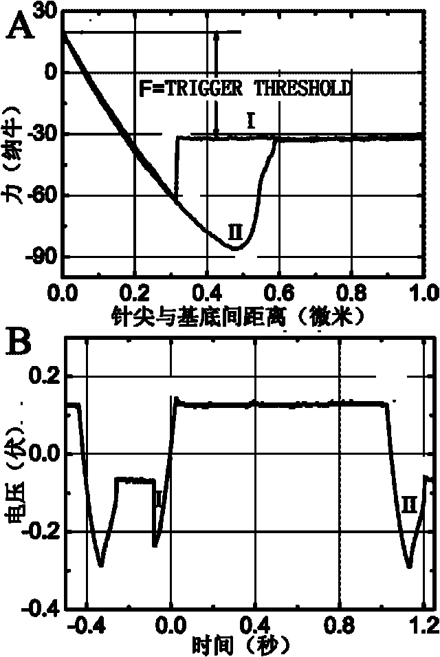
[0024] Etching is carried out in an environment with a relative humidity of 78% to 85% using an NSC-18 needle tip. The force used was 20nN, the sample was a silicon wafer treated with hexamethoxydisilane, and the ink was glycerin. Adjust TRIGGER TRESHOLD until figure 2 A force curve in the shape of A appears. If a force curve with a complete shape cannot be obtained, no matter how long the contact time is, the etching cannot be successful. figure 2 In B, it can be seen that the SURFACE DELAY time between point 3 and point 4 is 1s.

Embodiment 2

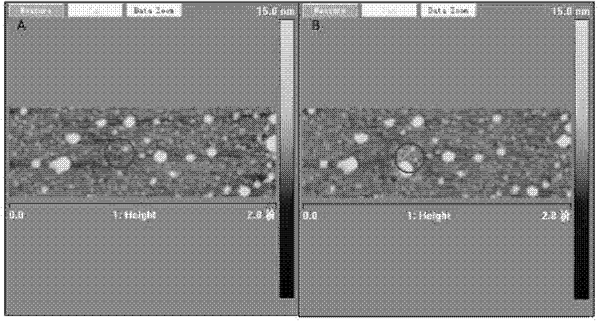
[0026] Etching is carried out in an environment with a relative humidity of 78% to 85% using an NSC-18 needle tip. The force used is 20nN, the sample is a silicon wafer after silane hydrophobic treatment, and the ink is glycerin. Points obtained by precisely controlling the residence time of the needle tip on the sample surface for 10 seconds. image 3 A is the pattern on the surface of the silicon wafer before etching, image 3 B is the pattern after etching. Comparing the two figures, it can be seen that under this condition, the method can successfully realize the etching of nano-dots.

Embodiment 3

[0028] Etching is carried out in an environment with a relative humidity of 43.4% to 46.5% using NSC-11 needle tips. Figure 4 A: The force used is 40nN, the sample is newly dissociated mica, the ink is glycerol, the residence time of the needle tip on the sample surface is precisely controlled to 20 seconds, and a nano-pattern with an interval of 400nm is obtained. Figure 4 B is the force used is 80nN, the sample is newly dissociated mica, the ink is horseradish peroxidase, and the residence time is 30 seconds, the obtained "口"-shaped nano-lattice array. Comparing the two figures, it can be seen that the nanodot array can be successfully obtained by this method; and because the force and time are well controlled, the shape and size of these dots are very consistent under the same operating parameters.


PUM


Abstract

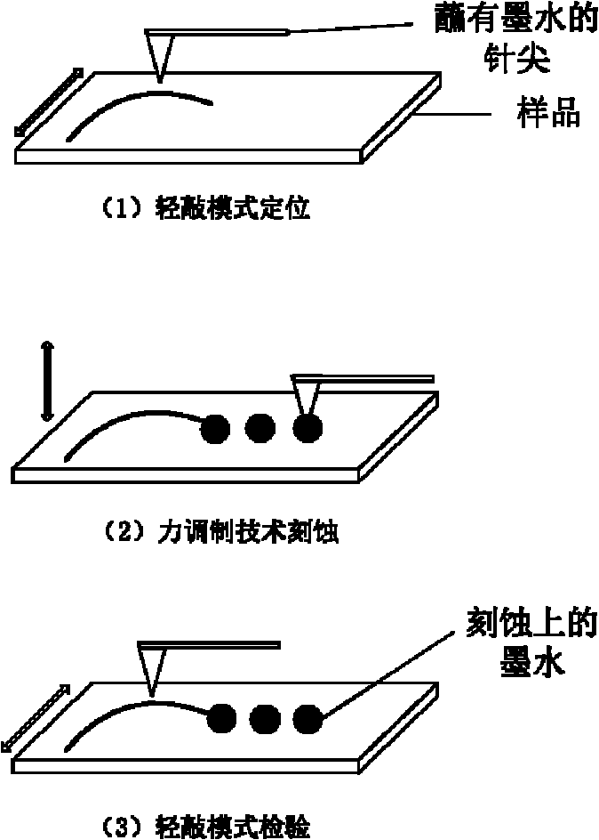
The invention provides a force modulation mode-based dip-pen nanolithography method in the technical field of nanometer manufacture, which is realized by combining a tapping mode and the force modulation technology, imaging by the tapping mode and lithographing on a setpoint by the force modulation technology. The method can accurately control the acting force and the acting time between a tip and a substrate, so the lithographing effect can be better controller, and the repeatability of lithographing operation is improved; and furthermore, the method can perform multi-point automatic location and dip-pen lithography operation once, is convenient and practical, and is advantageous to industrialization.

Description

technical field [0001] The invention relates to a method in the technical field of nano-manufacturing, in particular to a dip-pen nano-etching method based on a force modulation mode for nano-electronic devices and biochips. Background technique [0002] "Dip-pen nanolithography" is a nano-manufacturing technology that uses the tip of the atomic force microscope to transfer the substance adsorbed on the tip to the substrate through the action of the meniscus. People compare the needle point to a "pen", the substance on the needle point to "ink", and the etching process is analogous to writing with a pen on paper, so it is vividly called "dipping pen" nano-etching technology. Through this technology, people have been able to realize the transfer of biological macromolecules such as inorganic salts, small organic molecules and proteins on different substrates, and prepare functional graphics. (Science, 1999, 283: 661-663; Nature chemistry, 2009, 1: 353-358; PNAS, 2001, 98: 13...

Claims


Application Information

Patent Timeline
IPC IPC(8): B82B3/00B82Y40/00
Inventor 杨海军沈广霞郭守武
Owner SHANGHAI JIAO TONG UNIV
Learn More