Method for closed-loop power control of a road finishing machine or feeder and a road finishing machine or feeder comprising the same

A feeder and finishing machine technology, applied in road repair, transmission control, roads, etc., can solve the problems of reduced power demand, reduced internal combustion engine speed, etc., to achieve reduced resistance loss, constant power output, and maintain operation convenience. Effect

Active Publication Date: 2011-06-15
JOSEPH VOEGELE AG
View PDF6 Cites 2 Cited by
  • Summary
  • Abstract
  • Description
  • Claims
  • Application Information

AI Technical Summary

Problems solved by technology

Conversely, the speed of the internal combustion engine is reduced if the power demand of the drive, which requires a constant speed, is reduced

Method used


Image

  • Method for closed-loop power control of a road finishing machine or feeder and a road finishing machine or feeder comprising the same
  • Method for closed-loop power control of a road finishing machine or feeder and a road finishing machine or feeder comprising the same
  • Method for closed-loop power control of a road finishing machine or feeder and a road finishing machine or feeder comprising the same

Examples


Embodiment Construction

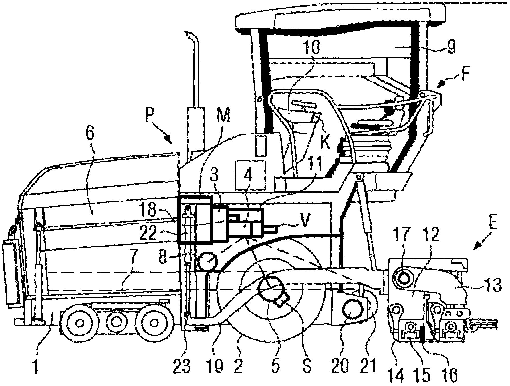
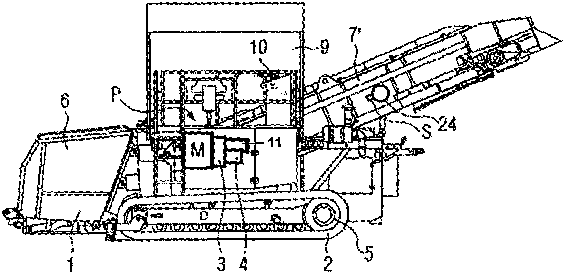
[0028] figure 1 Denotes a road finishing machine F for paving asphalt or concrete paving material for road laying. On the front side of the chassis 1 including the traveling mechanism 2 (wheel mechanism or crawler mechanism), a hopper 6 is set and a main power unit P is arranged behind it. The main power unit P includes an internal combustion engine M (usually a diesel engine), a pump transmission gear 3 and at least one variable displacement pump 4 arranged on the pump transmission gear 3 . In addition to the variable displacement pump 4 at least one further hydraulic pump 18 can also be provided. Furthermore, the generator 11 may be driven by the internal combustion engine M. As shown in FIG. On the driver's station 9 arranged on the chassis 1 there is provided, for example, a computerized control device 10 comprising a control panel K with a not shown main traction switch and other actuating and monitoring devices. At the rear of the chassis 1 , a transverse distribution...


PUM


Abstract

In the hydrostatic working operation of a road finishing machine or a feeder which comprises a primary power plant with an internal combustion engine (M) and several hydraulic variable displacement pumps, which are hydraulically connected to hydraulic motors of working components, and which possesses a computerized control device, the internal combustion engine is operated within its engine-specific characteristic map in response to the load condition by dynamic speed adaptation in a characteristic zone with optimal consumption, and the displacements (VsHP) of the variable displacement pumps are simultaneously automatically adapted for keeping the volume flow rates for the hydraulic motors constant. In the road finishing machine or the feeder, in the control device or connected to the same, a control loop for evaluating the load condition of the internal combustion engine and the current displacement of the variable displacement pumps is provided, by means of which the speed can be dynamically adjusted to or in a characteristic zone with optimal consumption, and simultaneously with the adjustment of the speed for keeping the volume flow rates for the hydraulic motors constant, thedisplacements of the variable displacement pumps can be automatically adapted.

Description

technical field [0001] The invention relates to a method according to the preamble of claim 1 and to a road finisher or feeder according to the preamble of claim 8 . Background technique [0002] In the hydraulic working operation of road finishers or feeders, the internal combustion engine is usually operated at a fixed speed level independent of the hydraulic or electrical power consumption of the working parts. The reason for this is that keeping all parameters constant and not giving any flexibility to the operation of the internal combustion engine is an experimentally proven goal, since prior closed-loop control techniques and the driver's reaction do not allow fast enough adaptation to changing paving conditions. This results in a substantially higher specific fuel consumption of the engine at a fixed high rotational speed level with a lower internal combustion engine load. Also for this load state, unnecessary drag losses occur, for example because fans and hydrauli...

Claims


Application Information

Patent Timeline
Patent Type & Authority Applications(China)
IPC IPC(8): E01C19/48
CPCB60W30/1882B60W10/06E01C19/48B60W10/103F16H61/47Y02T10/76
Inventor 托比亚斯·内尔拉尔夫·魏泽尔
Owner JOSEPH VOEGELE AG
Why Eureka
Try Eureka