
Antenna oscillator, antenna unit and antenna

A technology of antenna vibrator and antenna unit, which is applied in the field of communication, can solve the problems of thick antenna, large antenna volume, high thickness of half-wave vibrator antenna unit, etc., and achieve the effect of reducing cross-sectional area and thickness

Inactive Publication Date: 2011-06-15
SHENZHEN HUAWEI AGISSON ELECTRIC CO LTD
View PDF4 Cites 17 Cited by
  • Summary
  • Abstract
  • Description
  • Claims
  • Application Information

AI Technical Summary

Problems solved by technology

[0005] From the above introduction to the existing antenna unit, it is found that the existing technology has at least the following problems: Since the input impedance of the half-wave oscillator of the antenna unit itself is 75 ohms, and the output impedance is 50 ohms, it is necessary to increase impedance matching on the balun part, and an impedance matching section is a quarter wavelength, so it also determines that the height of the half-wave dipole antenna must meet a quarter wavelength to achieve impedance matching
In turn, the thickness of the antenna is still very thick. In addition, due to the current concentration on the vibrator, the induced current can only be excited in a small area of ​​the reflector, resulting in a wider beam width. In order to achieve the required beam width, only through Increase the reflector width to achieve
Therefore, due to these two reasons, the thickness of the existing half-wave dipole antenna unit is relatively high, and the width of the reflecting plate matched with it is relatively wide, resulting in a large volume of the antenna

Method used


Image

  • Antenna oscillator, antenna unit and antenna
  • Antenna oscillator, antenna unit and antenna
  • Antenna oscillator, antenna unit and antenna

Examples


Embodiment 1

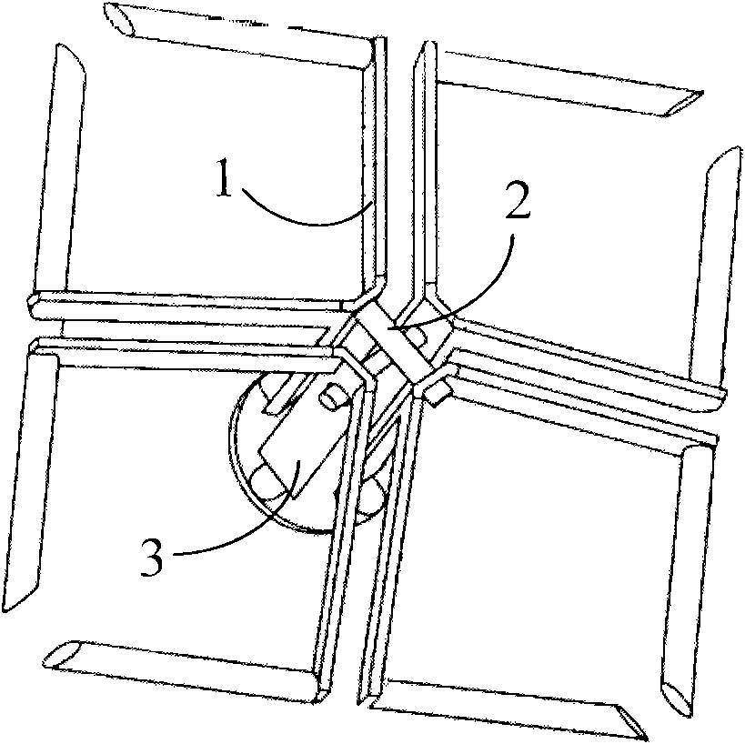
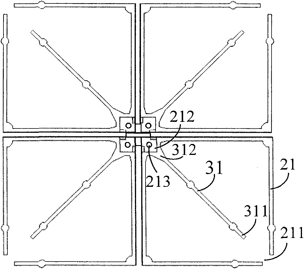
[0033] Embodiment 1 provides an antenna vibrator, which can be used in an antenna unit, such as figure 2 As shown, the antenna vibrator includes two pairs of vibrators, and each pair of vibrators is composed of two frame-shaped vibrators 21. The frame-shaped vibrator can adopt various structural forms such as square structure, rectangular structure, polygonal structure, elliptical structure, and circular structure. The frame-shaped vibrator 21 is provided with an opening 211, such as figure 2 The frame-shaped vibrator shown in the above adopts a square frame vibrator, and the opening is set at one corner of the square frame vibrator; the frame-shaped vibrator 21 is provided with a wire vibrator 31, and the wire vibrator 31 can be connected with the frame-shaped vibrator where it is located. 21 are on the same plane, the line vibrator can be a solid structure, or a frame structure, in this embodiment Figure 8 The linear vibrator 31 adopts a rectilinear columnar structure vi...

Embodiment 2

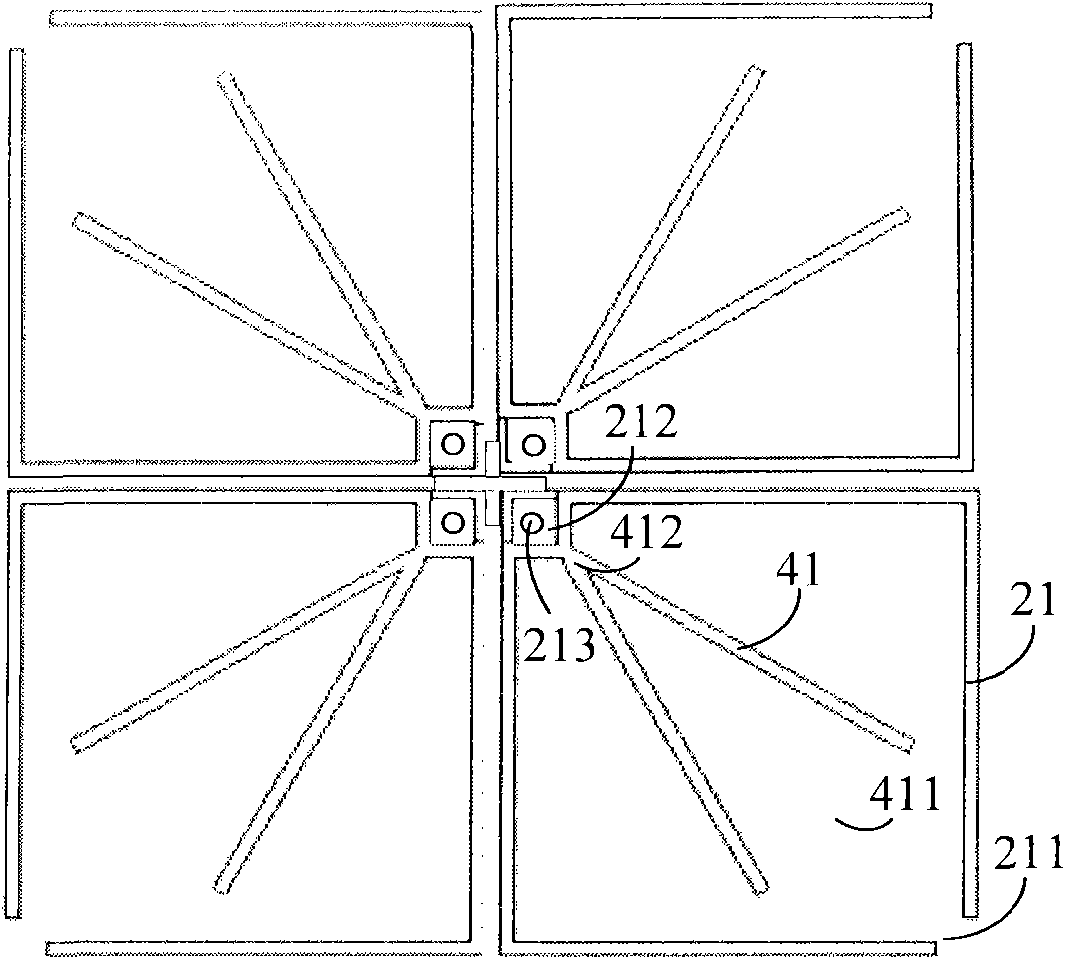
[0038]The second embodiment provides an antenna vibrator, which can be used in an antenna unit. The structure of the antenna vibrator is basically the same as that of the antenna vibrator given in the first embodiment. The antenna vibrator also includes two pairs of vibrators, each pair of vibrators consists of two frames shaped vibrator 21, and a line vibrator is arranged in each frame vibrator 21, and the line vibrator is also set on the diagonal line where the corner end of the opening 211 of the frame vibrator 21 is located, which is the same as the antenna vibrator given in Embodiment 1 The difference is that the wire vibrator set in the frame-shaped vibrator 21 uses two or more straight vibrator pairs formed by connecting one end at a certain angle, and the vibrator pair is installed in the frame-shaped vibrator 21 , and is symmetrical along the diagonal of the frame oscillator; for example image 3 As shown, two straight vibrators are connected to form a V-shaped line v...

Embodiment 3

[0041] The third embodiment provides an antenna vibrator, which can be used in the antenna unit. The structure of the antenna vibrator is basically the same as that of the antenna vibrator given in the first and second embodiments. The antenna vibrator also includes two For the vibrator, a line vibrator is arranged in each frame vibrator, and the line vibrator is also set on the diagonal line where the corner end of the opening of the frame vibrator is located, which is different from the antenna vibrator given in Embodiments 1 and 2. Yes, the wire vibrator in the frame-shaped vibrator adopts a quadrilateral or polygonal structure vibrator. Such as Figure 4 As shown, a quadrilateral wire vibrator is taken as an example for illustration. The quadrilateral wire vibrator 51 is symmetrically arranged in the frame vibrator 21 along the diagonal line of the frame vibrator. One end of the quadrilateral wire vibrator 51 is opposite to the opening 211 at the corner end of the frame vi...


PUM


Abstract

The embodiment of the invention provides an antenna oscillator, an antenna unit and an antenna, belonging to the technical field of communication. The antenna oscillator comprises two pairs of oscillators; each pair of oscillators comprises two frame oscillators; each frame oscillator is provided with an opening and internally provided with a linear oscillator; one end of the linear oscillator isopposite to the opening of the frame oscillator and keeps a certain distance; the other end of the linear oscillator is electrically connected with a body at the opposite end of the opening of the frame oscillator; the two frame oscillators of each pair of oscillators are fixedly connected through the electrically connected linear oscillators in each frame oscillator; and the two oscillators are mutually connected through parts for fixing linear oscillators in the frame oscillators in each pair of oscillators. The antenna oscillator can reduce the plane beam width of the oscillators so that the antenna unit made by utilizing the antenna oscillator can form the needed beam width by only matching with a smaller reflection plate, and the made antenna is minimized.

Description

technical field [0001] The invention relates to the technical field of communication, in particular to an antenna dipole, an antenna unit and an antenna. Background technique [0002] The antenna is an energy conversion device in the mobile communication system. It is generally used in conjunction with the base station. The electromagnetic wave signal emitted by the mobile station of the base station is converted into an electrical signal by the antenna for processing by the base station; conversely, the base station converts the electrical signal into an electromagnetic signal through the antenna. The signal propagates in the free space, and the mobile station can receive it randomly, so as to realize the two-way communication of the communication system. With the development of the operator's network, more and more antennas need to be installed at the same site. A large number of antennas need to be installed on a steel tower or pole. If the antenna is large, it will take ...

Claims


Application Information

Patent Timeline
Patent Type & Authority Applications(China)
IPC IPC(8): H01Q1/36H01Q13/08H01Q19/10
Inventor 艾鸣谢国庆唐涛杨铁军周海明
Owner SHENZHEN HUAWEI AGISSON ELECTRIC CO LTD
Learn More