Digital microwave radio remote unit coverage system and method

A remote radio frequency and digital microwave technology, which is applied in transmission systems, radio transmission systems, electrical components, etc., can solve the problems of restricting the popularization and application of remote radio frequency coverage technology, lack of flexibility in networking, and high requirements for the laying environment. The effect of low environmental requirements, solving the huge difference in transmission bandwidth, and improving construction efficiency

Inactive Publication Date: 2011-06-15
COMBA TELECOM SYST CHINA LTD
View PDF5 Cites 24 Cited by
  • Summary
  • Abstract
  • Description
  • Claims
  • Application Information

AI Technical Summary

Problems solved by technology

[0004] The above-mentioned digital optical fiber radio remote coverage system uses optical fiber as the signal transmission medium between DAU and DRU. Since optical fiber is a wired transmission medium, it has high requirements for the laying environment, high engineering costs, slow construction efficiency, and lack of flexibility in networking. It is difficult to practice in some areas where optical link resources are limited or where it is not easy to lay optical fibers
The above shortcomings of the digital optical fiber remote radio coverage system greatly limit the popularization and application of radio remote coverage technology

Method used


Image

  • Digital microwave radio remote unit coverage system and method
  • Digital microwave radio remote unit coverage system and method
  • Digital microwave radio remote unit coverage system and method

Examples


Embodiment 1

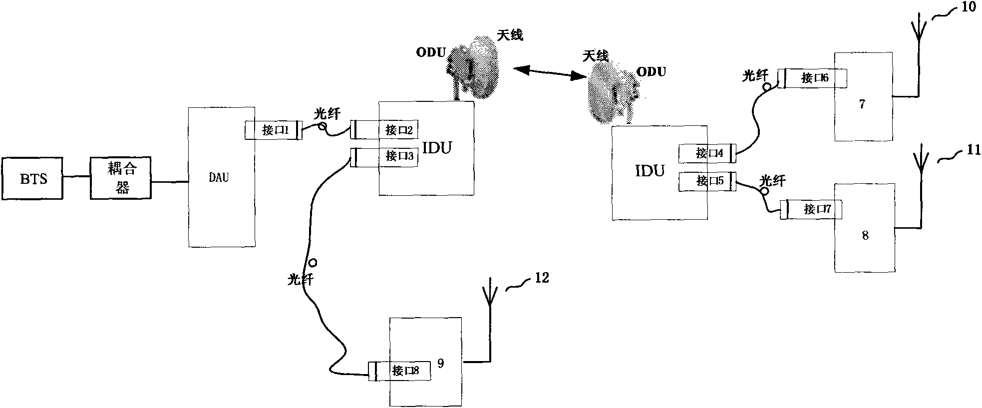
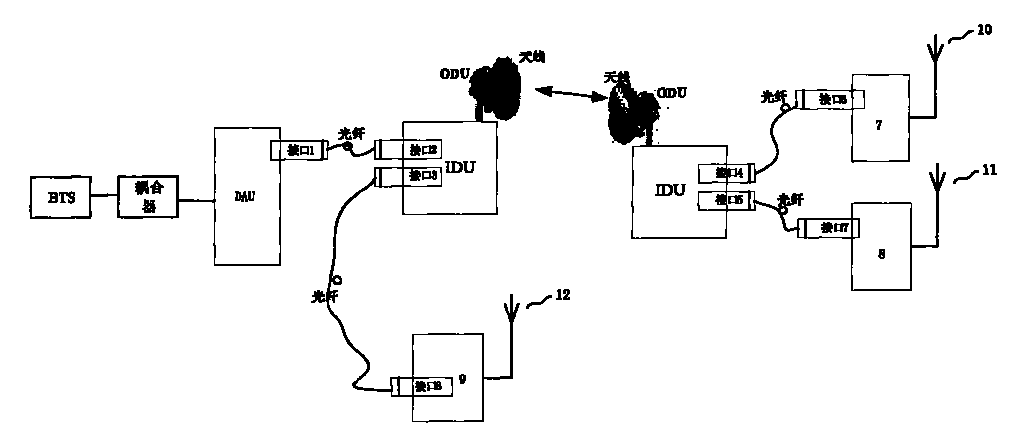
[0042] Such as figure 2 As shown, the digital microwave radio remote coverage system in this embodiment is a hybrid networking system with three DRUs (DRU7, DRU8, and DRU9).

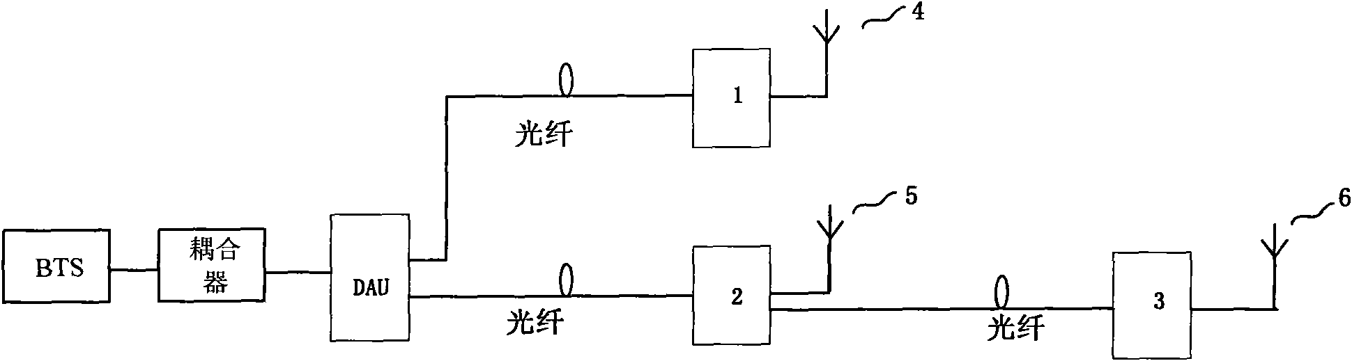
[0043] The digital microwave radio frequency remote coverage system in this embodiment includes DAU, DRU7, DRU8 and DRU9, and the BTS is connected to the DAU through a coupler. The DRU7, DRU8 and DRU9 are respectively connected to the coverage antenna 10, the coverage antenna 11 and the coverage antenna 12 to realize area coverage.

[0044] The digital microwave radio frequency remote coverage system of this embodiment also includes a near-end microwave transmission unit and a far-end microwave transmission unit. The IDU of the transmission unit is connected to the ODU and the antenna in sequence, the antenna of the remote microwave transmission unit is connected to the ODU and the IDU in sequence, and the antenna of the near-end microwave transmission unit communicates with the antenna of the far-end ...


PUM


Abstract

The invention discloses a digital microwave radio remote unit (RRU) coverage system and a digital microwave RRU coverage method. The structure of the system comprises a digital access control unit (DAU), a digital radio remote unit (DRU) and a coverage antenna. The system is characterized by also comprising a near-end microwave transmission unit and a far-end microwave transmission unit, wherein both the near-end microwave transmission unit and the far-end microwave transmission unit comprises an indoor microwave unit (IDU), an outdoor microwave unit (ODU) and an antenna; the IDU of the near-end microwave transmission unit is sequentially connected with the ODU and the antenna; the antenna of the far-end microwave transmission unit is sequentially connected with the ODU and the IDU; the antenna of the near-end microwave transmission unit is communicated with the antenna of the far-end microwave transmission unit by adopting microwave; and the IDU of the near-end microwave transmission unit is connected with the DAU by adopting a standard base station interface, and the IDU of the far-end microwave transmission unit is connected with the DRU by adopting the standard base station interface. The microwave is used as a signal transmission medium between the DAU and the DRU so as to realize wireless communication between the DAU and the DRU.

Description

technical field [0001] The invention relates to remote radio frequency coverage technology, in particular to a digital microwave remote radio frequency (RRU) coverage system and method. Background technique [0002] The traditional radio remote coverage solution is generally implemented by means of digital optical fiber remote radio. The traditional digital optical fiber remote radio coverage system structure includes a digital access control unit (DAU) and several digital remote radio units (DRU). The base station (BTS) is connected to the DAU through a coupler. The DAU is connected to the DRU by optical fiber. Realize extended coverage of base station signals. The traditional digital fiber radio remote coverage system can adopt star networking, daisy chain networking, or a hybrid networking combining star networking and daisy chain networking. In the pure daisy-chain networking mode or the daisy-chain networking mode in the mixed networking mode, the upper-level DRU is c...

Claims


Application Information

Patent Timeline
Patent Type & Authority Applications(China)
IPC IPC(8): H04B7/00H04W88/08
Inventor 朱勤罗漫江刘庆国冯贤光
Owner COMBA TELECOM SYST CHINA LTD
Why Eureka
Try Eureka