Eureka AIR delivers breakthrough ideas for toughest innovation challenges, trusted by R&D personnel around the world.

Aeroacoustic rotor blade for a wind turbine, and wind turbine equipped therewith

A technology of rotor blades and wind power equipment, applied in the field of wind power equipment, can solve the indispensable pursuit of reducing the noise generated by wind power equipment, and achieve the effects of reduced noise emission, strong noise reduction, and low power loss

Inactive Publication Date: 2011-06-22
西格弗里德·米克勒 +1
View PDF12 Cites 3 Cited by
  • Summary
  • Abstract
  • Description
  • Claims
  • Application Information

AI Technical Summary

Problems solved by technology

[0006] Therefore, the pursuit of reducing the noise generated by wind power equipment cannot be lacking.

Method used


Image

  • Aeroacoustic rotor blade for a wind turbine, and wind turbine equipped therewith
  • Aeroacoustic rotor blade for a wind turbine, and wind turbine equipped therewith
  • Aeroacoustic rotor blade for a wind turbine, and wind turbine equipped therewith

Examples


Embodiment Construction

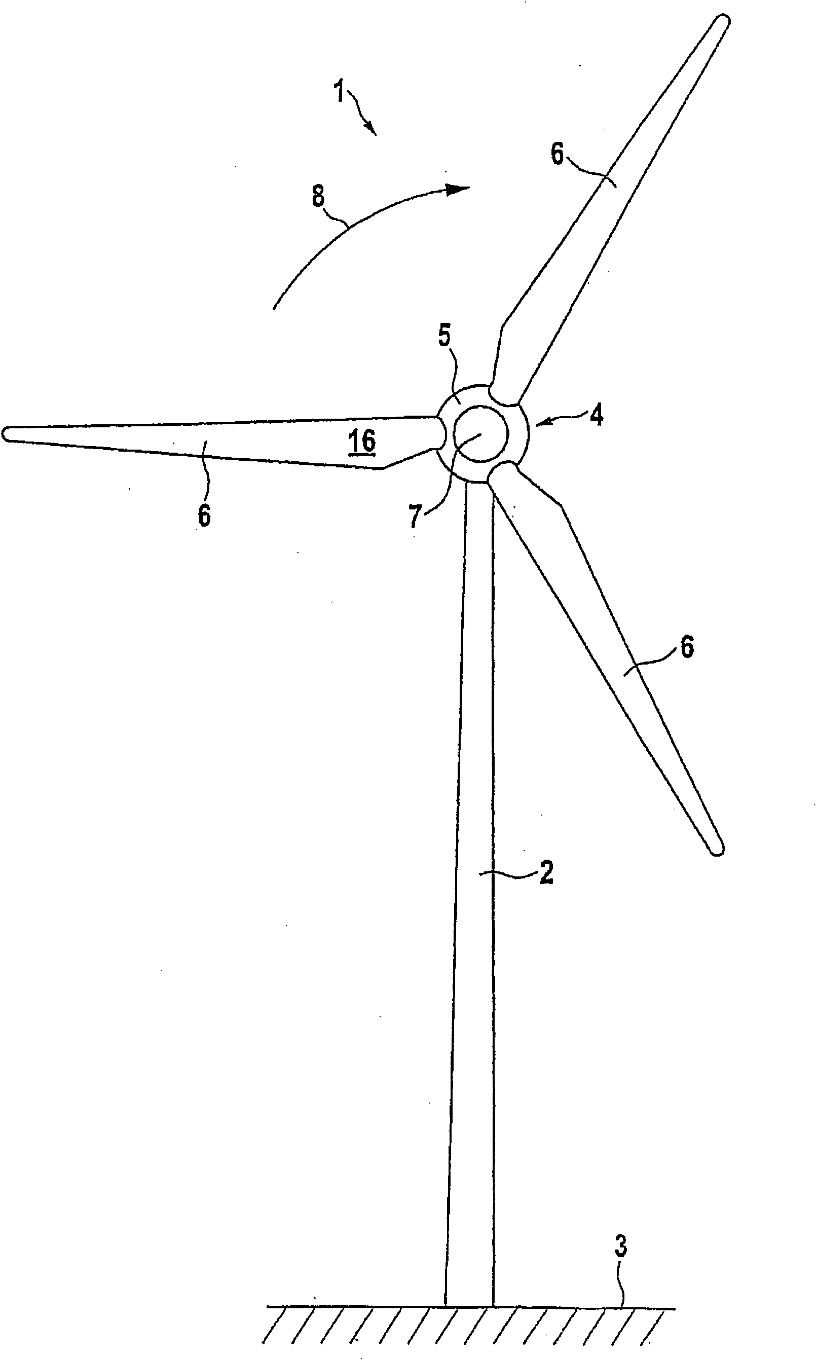
[0036] figure 1 Shown is a wind power installation 1 according to the invention, which consists of a tower 2 fixedly anchored in a foundation 3 with a bottom region and a rotor 4 arranged in the top region of the tower 2, which rotates around the The axis of rotation 7 of the viewing plane rotates in the direction of the arrow 8 . The rotor 4 has a hub 5 rotatably supported on top of the tower 2 and coupled to a generator for generating electricity. The rotor blades 6 are connected to the rotor 4 in the region of the hub 5 .

[0037] exist figure 2 The top view of the suction side 9 shows the rotor blades 6 of the rotor 4 on a larger scale. The longitudinal extension of the rotor blade 6 along its longitudinal axis 10 is denoted as length L and is determined by the distance of the blade joint 11 from the blade end 12 . The relative length x / L represents any position starting from the blade joint 11 between the blade joint 11 and the blade end 12 .

[0038] also figure ...


PUM


Abstract

A rotor blade and a wind turbine is provided that has such a rotor blade, wherein the absolute length of the rotor blade extends from the blade attachment to the blade tip and the relative blade length proceeds from the blade attachment. The rotor blade is divided into an inner longitudinal section associated with the blade attachment and an outer longitudinal section associated with the blade tip, wherein the transition from the inner longitudinal section to the outer longitudinal section defines the cross-sectional plane E0, and the blade tip defines the cross-sectional plane EE. As a function of the relative blade length, the rotor blade has a specific aerodynamic profile with a chord t, a twist theta, a relative thickness d / t, a relative curvature f / t, and a relative trailing edge thickness h / t. In order to reduce acoustic emissions without having to accept appreciable losses in performance, it is proposed according to the invention that the cross-sectional plane E0 is located at a relative blade length in the range between 0.80 and 0.98, the blade chord of the aerodynamic profile in the cross-sectional plane EE is at least 60% of the blade chord t of the aerodynamic profile in the cross-sectional plane E0, and the blade twist of the aerodynamic profile in the cross-sectional plane EE is greater than the blade twist - of the aerodynamic profile in the cross-sectional plane E0.

Description

technical field [0001] The invention relates to a rotor blade for a wind power installation according to the preamble of claim 1 and to a wind power installation according to the preamble of claim 22 . Background technique [0002] Wind power is gaining increasing significance as a source of energy when producing energy from renewable sources. The reason for this lies in the limited availability of primary raw materials, which, in the case of an increased energy demand, leads to a shortage of the energy obtained therefrom and thus to an expensive cost. Furthermore, primary raw materials, when converted into energy, cause severe carbon dioxide emissions, which are believed to be responsible for the dramatic climate change of the past few years. There is thus an awareness shift towards the use of renewable energies on the part of the population. [0003] Known wind power installations for the production of energy comprise a tower, at the end of which a rotor with radially or...

Claims


Application Information

Patent Timeline
Patent Type & Authority Applications(China)
IPC IPC(8): F03D1/06
CPCF05B2240/301Y02E10/72Y02E10/721F03D1/0641F05B2260/96
Inventor 西格弗里德·米克勒沃尔特·凯勒
Owner 西格弗里德·米克勒
Why Eureka
Eureka Blog
Learn More