Multi-light path optical fiber fluorescent sensor
A fluorescence sensor, multi-optical path technology, applied in fluorescence/phosphorescence, material excitation analysis, etc., can solve the problems of long measurement period, increased cost, impracticality, etc., and achieve the effect of suppressing background interference, improving receiving efficiency, and simple structure
- Summary
- Abstract
- Description
- Claims
- Application Information
AI Technical Summary
Problems solved by technology
Method used
Image

Examples
Embodiment 1
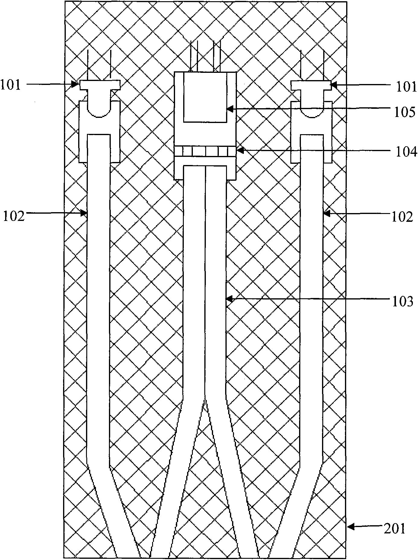
[0028] Such as figure 1 As shown, a dual optical path optical fiber fluorescence sensor for direct detection of fluorescent substances, its structure includes two excitation light sources 101 (light emitting diodes), two excitation optical fibers 102, and two receiving optical fibers 103;
[0029] The incident end of each excitation fiber 102 is respectively coupled with a light source 101 in one-to-one correspondence;
[0030] Each receiving optical fiber 103 is paired with an exciting optical fiber 102 respectively, and the incident end face of the receiving optical fiber 103 and the outgoing end face of the corresponding exciting optical fiber 102 are in the same plane, and the distance between their end faces is 0-5mm;
[0031] The outgoing ends of the two receiving optical fibers 103 are coupled to the light window of the photoelectric conversion device 105 through the optical filter 104 .
[0032] The excitation light source 101, excitation optical fiber 102, receiving ...
Embodiment 2
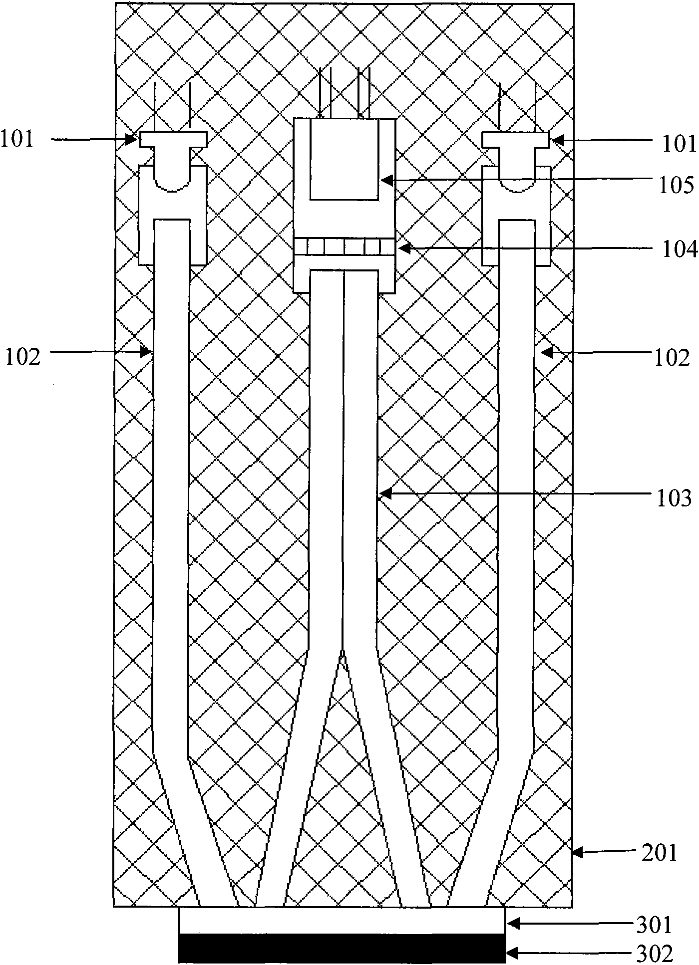
[0042] Such as figure 2 As shown, a 3-light-path fiber-optic fluorescence sensor for indirect detection of non-fluorescent substances,
[0043] The difference from Embodiment 1 is that the optical paths are 3 groups, there are 3 excitation light sources 101 coupled with the incident ends of 3 excitation fibers 102, and 3 receiving fibers 103 are combined with optical filters 104 and photoelectric conversion devices 105. coupling.
[0044]A fluorescent sensing film substrate 301 and a fluorescent sensing film 302 are sequentially arranged on the planar surface where the outgoing end of the excitation optical fiber 102 and the incident end of the receiving optical fiber 103 are located, and the sensing film substrate 301 is attached to the end surface of the sensor probe. Tight and secure.
[0045] The excitation light source 101, excitation optical fiber 102, receiving optical fiber 103, optical filter 104 and photoelectric conversion device 105 of the optical fiber sensor a...
PUM
 Abstract
Description
Claims
Application Information
PatSnap Eureka turns technology decisions into work you can execute. Powered by our Innovation Knowledge Graph, it runs expert workflows across engineering, life sciences, materials and intellectual property. Get your review-ready output in minutes.


