Plastic pipe molding equipment

A technology for forming equipment and plastic pipes, which is applied in the direction of tubular objects, other household appliances, household appliances, etc. It can solve the problems of blockage at the outlet end of the heating cylinder, inaccurate quality, and slow response, so as to reduce performance requirements and ensure accuracy. sex, the effect of avoiding errors

Inactive Publication Date: 2011-06-29
NINGBO FANGLI GRP
View PDF6 Cites 6 Cited by
  • Summary
  • Abstract
  • Description
  • Claims
  • Application Information

AI Technical Summary

Problems solved by technology

[0004] However, the prior art plastic pipe molding equipment has the following defects: firstly, during the production process, the outlet end of the heating cylinder is often blocked, so that although the rotating speed of the main motor remains unchanged, the amount of material extruded from the outlet end is actually The raw materials are greatly reduced. At this time, the rotation speed of the traction motor obtained according to the rotation speed of the main motor obviously cannot guarantee that the meter weight and thickness of the pipe meet the design requirements, that is, the thickness and meter weight of the pipe formed at this time must be much smaller than the target value; secondly , because people rely on the speed of the main motor to calculate the volume of the raw material extruded from the heated cylinder, and then multiply the volume by the density to obtain the mass of the raw material extruded from the heated cylinder, and there are gaps between the solid raw material particles, so The density of these raw materials is inherently uneven, and the mass obtained by multiplying the volume by the density is not accurate, so the final meter weight and thickness cannot be guaranteed to be accurate; again, by inputting the speed of the main motor, and then manually according to the speed of the main motor Input the speed of the traction motor, and the process of manually adjusting the speed of the traction motor often has a lag and slow response

Method used


Image

  • Plastic pipe molding equipment
  • Plastic pipe molding equipment
  • Plastic pipe molding equipment

Examples


Embodiment Construction

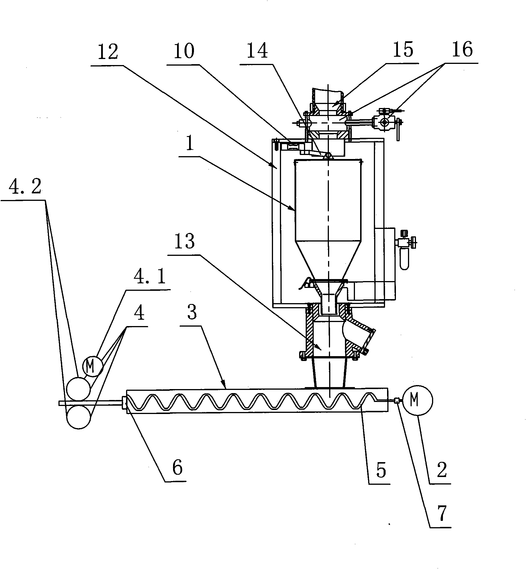
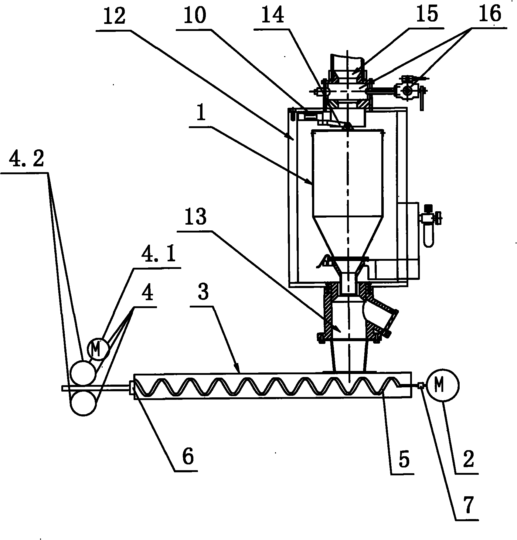
[0024] The present invention will be further described below in conjunction with the accompanying drawings and specific embodiments.

[0025] Such as figure 1 , figure 2 As shown, the plastic pipe molding equipment of the present invention includes a hopper 1, a main motor 2, a horizontally arranged heating cylinder 3 and a tractor 4. The horizontally arranged heating cylinder 3 generally refers to the horizontally arranged heating cylinder 3. The lower end of the hopper 1 communicates with the inlet end of the heating cylinder 3 . A screw 5 is arranged in the axial direction of the heating cylinder 3, and the screw 5 is fixed to the output shaft of the main motor 2, that is, a screw 5 is arranged inside the heating cylinder 3 along the axial direction, and one end of the screw 5 is connected to the output shaft of the main motor 2. The output shaft is fixed. The outlet end of the heating cylinder 3 is provided with a pipe forming die 6, and the pipe forming die 6 is a con...


PUM


Abstract

The invention discloses plastic pipe molding equipment which comprises a hopper (1), a main motor (2), a heating cylinder body (3) and a traction engine (4), wherein, the heating cylinder body (3) is arranged transversely; the lower end of the hopper (1) is communicated with an entry end of the heating cylinder body (3); a screw bolt (5) is arranged in the axial direction of the heating cylinder body (3); the screw bolt (5) is fixed on an output shaft of the main motor (2); a pipe forming die (6) is arranged at an outlet end of the heating cylinder body (3); the traction engine (4) comprises a traction motor (4.1), a crawler (4.2), a PLC (Programmable Logic Controller) chip, a motor speed governor and a hopper mass variation value acquisition device, wherein, the crawler (4.2) is driven by the traction motor (4.1); both the motor speed governor and the hopper mass variation value acquisition device are electrically connected with the PLC chip; and the motor speed governor is electrically connected with the traction motor (4.1). The plastic pipe molding equipment can control the weight per meter and the thickness of pipes accurately.

Description

technical field [0001] The invention relates to the field of industrial production lines for preparing plastic pipes, in particular to plastic pipe forming equipment. Background technique [0002] The plastic pipe forming equipment in the prior art includes a hopper, a main motor, a heating cylinder arranged horizontally and a tractor. The output shaft of the heating cylinder is fixed, and the outlet end of the heating cylinder is provided with a pipe forming mold. The tractor includes a traction motor and a crawler driven by the traction motor. [0003] The working principle of the plastic pipe forming equipment is as follows: solid raw material particles fall into the hopper and fill the hopper, and then fall from the hopper into the heating cylinder. At this time, the screw is driven by the main motor to rotate the plastic particles in the heating cylinder to As the outlet end moves, the particles gradually melt in the heating cylinder, and are pushed through the pipe fo...

Claims


Application Information

Patent Timeline
Patent Type & Authority Applications(China)
IPC IPC(8): B29C47/92B29L23/00B29C48/92
CPCB29C48/92B29C2948/9259B29C2948/92933B29C2948/92952
Inventor 周涛
Owner NINGBO FANGLI GRP
Why Eureka
Try Eureka