
Automatic calibration method and device

An automatic calibration and calibration gas technology, which is applied in the direction of measuring devices, instruments, scientific instruments, etc., can solve the problems of low automation, fast consumption of calibration gas, high use and maintenance costs, etc., and achieve high automation, large dilution ratio, and work Small amount of effect

Active Publication Date: 2011-06-29
杭州谱育检测有限公司
View PDF1 Cites 22 Cited by
  • Summary
  • Abstract
  • Description
  • Claims
  • Application Information

AI Technical Summary

Problems solved by technology

[0009] 1. Low degree of automation and difficulty in miniaturization of instruments
[0010] Since the dynamic calibrator and the chromatographic analyzer are two sets of instruments, the preparation of gases at various concentration levels, the control of the path between the dynamic calibrator and the chromatographic analyzer, and the generation of the final calibration curve all require manual operations, and the steps are cumbersome. Remote control and automated calibration are difficult;
[0011] The calibrator is bulky and difficult to miniaturize;
[0012] 2. The range of dilution ratio is small, and the cost of use and maintenance is high
[0013] The flow rate range of the flowmeter equipped with the dynamic calibrator itself is limited, resulting in a limited range of the dilution ratio between the dilution gas and the standard gas; in order to obtain a high-concentration calibration gas, it is necessary to use a larger standard gas flow rate, so that the standard gas consumption is fast ; or when the flow rate is set according to the demand, the fixed configuration of the dynamic calibrator cannot reach the required flow rate, so that the calibration cannot be carried out as expected; to achieve the calibration of a large dilution ratio range, the flow meter needs to be replaced frequently, resulting in high use and maintenance costs ;
[0014] 3. It is difficult to carry out personalized design for each chromatographic analyzer
[0015] Since different chromatographic analyzers are suitable for different occasions, the dilution ratio ranges are different when calibrating the corresponding chromatographic analyzers, so that the use of one dynamic calibrator cannot meet the calibration requirements of multiple chromatographic analyzers at the same time; thus making each It is difficult to personalize the design of a chromatographic analyzer

Method used


Image

  • Automatic calibration method and device
  • Automatic calibration method and device
  • Automatic calibration method and device

Examples


Embodiment 1

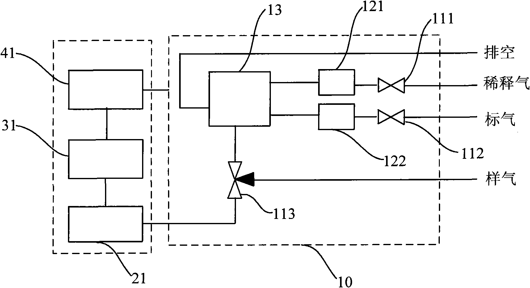
[0055] see figure 1 , an automatic calibration device, comprising an analytical instrument, a calibration unit 10, a measurement unit 21, a processing unit 31 and a control unit 41;

[0056] The calibration unit 10, the measurement unit 21, the processing unit 31 and the control unit 41 are all arranged inside the analytical instrument; the analytical instrument is a chromatography analyzer;

[0057] The calibration unit 10 includes a valve, a flow controller 121, a flow controller 122 and a gas mixing chamber 13;

[0058] The valve includes two two-way normally closed solenoid valves 111, a solenoid valve 112 and a two-position three-way solenoid valve 113;

[0059] The flow controller 121 and the flow controller 122 are mass flow meters MFC or electronic flow controllers EFC, which in this embodiment are EFCs;

[0060] The gas mixing chamber 13 is connected to the dilution gas through a flow controller 121, and connected to the calibration gas through a flow controller 122...

Embodiment 2

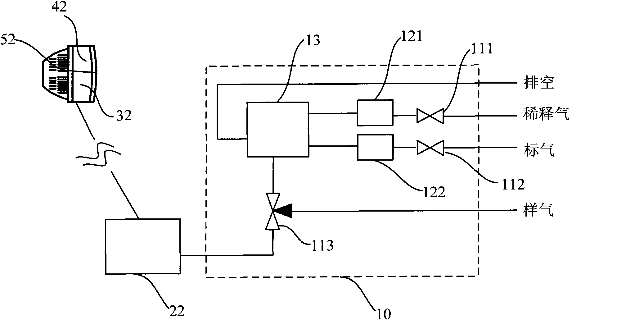
[0086] see image 3 , an automatic calibration device, different from the automatic calibration device described in embodiment 1 is:

[0087] The automatic calibration device also includes a remote server 52, and the control unit and the analysis unit can be arranged in the analytical instrument one, and one in the remote server; they can also be arranged in the analytical instrument; they can also be arranged in the remote server;

[0088] In this embodiment, the control unit 42 and the processing unit 32 are set in the remote server 52;

[0089] The automatic calibration device is equipped with flow controllers of different flow ranges to realize the ratio of different dilution concentrations of standard gas and dilution gas;

[0090] An alarm module is set in the processing unit 32, and the processing unit 32 judges whether the flow rate of the calculated standard gas and / or dilution gas exceeds the range range of the flow controller for controlling the corresponding gas f...

Embodiment 3

[0105] see Figure 4 , an automatic calibration device, different from the automatic calibration device described in embodiment 2 is:

[0106] There are multiple analytical instruments, wherein the calibration unit 10 is built into one analytical instrument, and the solenoid valve and the flow controller are controlled by the control unit 43 in the remote server 53; the exhaust air of the gas mixing chamber 13 In this embodiment, the analytical instruments are four chromatographic analyzers, and the calibration unit 10 is built in the chromatographic analyzer 1.

[0107] An automatic calibration method, different from the calibration method described in embodiment 2 is:

[0108] In step a, the automatic calibration device described in this embodiment is provided;

[0109] In step b, the processing unit 43 calculates the flow rate of the diluent gas and the standard gas, and when measuring each concentration point, at least one chromatographic analyzer performs calibration and ...


PUM


Abstract

The invention relates to an automatic calibration method. The method comprises the following steps of: a, introducing a gas sample into an analytical instrument and continuously analyzing the gas sample; b, when calibration is needed, switching a gas flow path to a calibration flow path by a control unit, controlling the flow of standard gas and diluent gas by the control unit, preparing calibration gas with specified concentration, and introducing calibration gas into the analytical instrument to obtain calibration data; and generating a new calibration result according to the calibration data; and c, switching the gas flow path to a gas sample flow path by the control unit, and continuously analyzing the gas sample by using the new calibration result until calibration is needed. The invention also provides an automatic calibration device. The invention has the advantages that: a dilution ratio range is wide, the volume is small, remote control and automatic calibration can be realized and the like.

Description

technical field [0001] The invention relates to an automatic calibration method and device, in particular to an automatic calibration method and device applied in the field of chromatography. Background technique [0002] On-line chromatographic analyzers used for environmental monitoring usually use the external standard calibration method for quantitative analysis of analytes, that is, before measuring the actual sample, first analyze the signal value of each component to be measured in the standard gas with known concentration, and then use this The signal value and the ratio of the measured component to the standard gas concentration are used as the conversion factor in the quantitative analysis. [0003] Usually, after this type of instrument has been in operation for a long time, due to changes in environmental conditions and detector response attenuation, the signal value of the instrument for the same concentration of gas will drift, which will seriously affect the a...

Claims


Application Information

Patent Timeline
IPC IPC(8): G01N30/02
Inventor 朱文明肖旷刘立鹏李天麟
Owner 杭州谱育检测有限公司
Learn More