Laser frequency stabilizing device for atomic clock

A technology of atomic clocks and lasers, applied in the field of atomic clocks, to achieve the effect of improving frequency stability

Inactive Publication Date: 2011-06-29
NAT TIME SERVICE CENT CHINESE ACAD OF SCI
View PDF4 Cites 20 Cited by
  • Summary
  • Abstract
  • Description
  • Claims
  • Application Information

AI Technical Summary

Problems solved by technology

[0003] The technical problem to be solved by the present invention is to overcome the deficiencies of existing laser frequency stab

Method used


Image

  • Laser frequency stabilizing device for atomic clock
  • Laser frequency stabilizing device for atomic clock

Examples


Embodiment 1

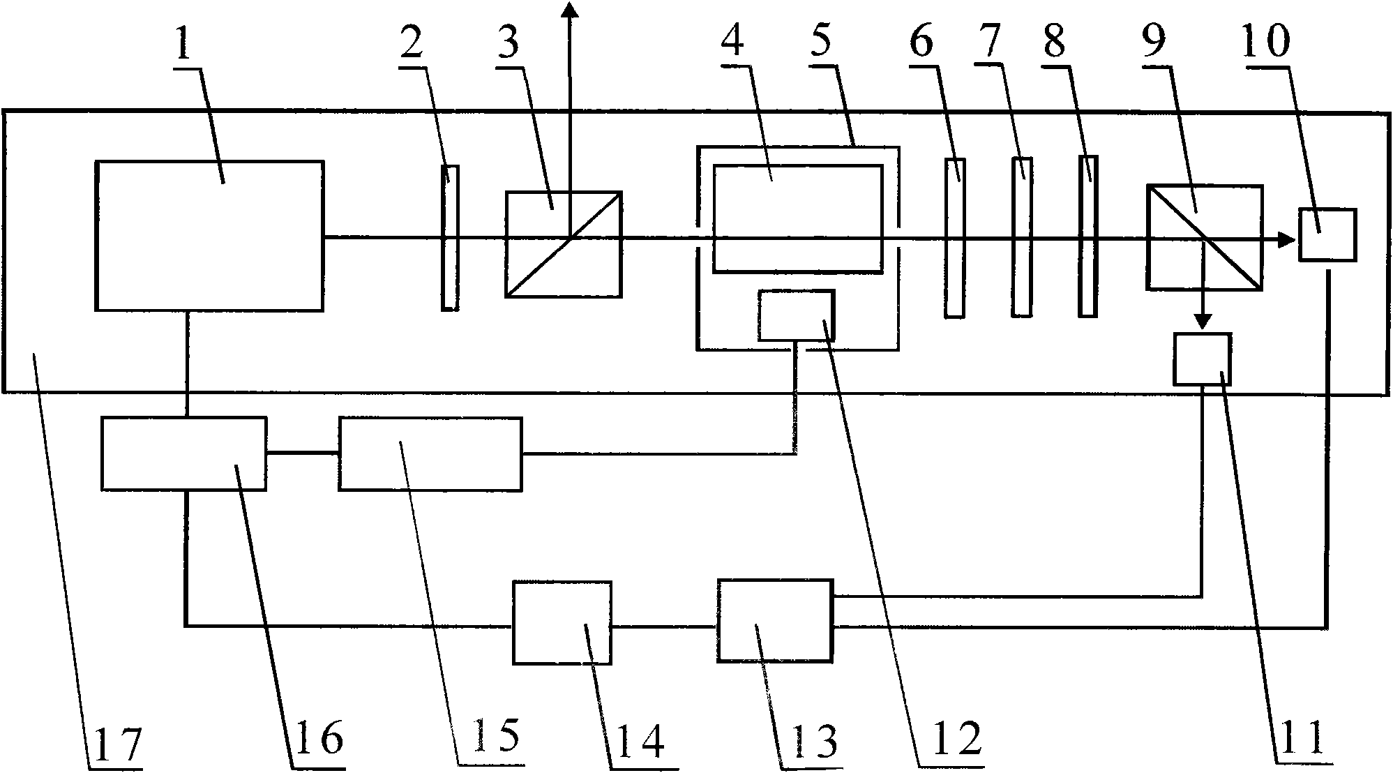
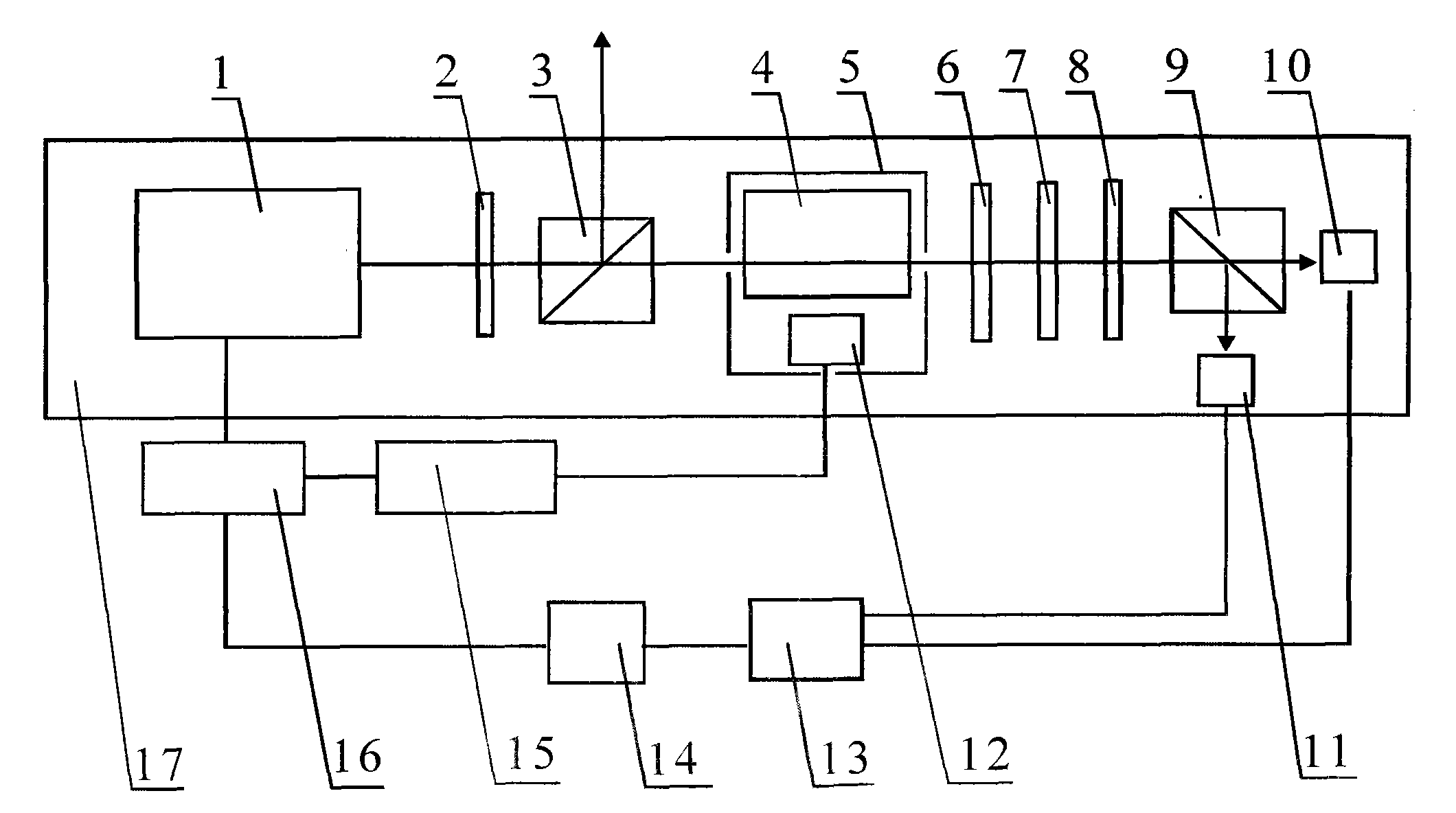
[0016] exist figure 1 Among them, the laser frequency stabilization device for the atomic clock of the present embodiment consists of a laser 1, a half-wave plate 2, a first polarization beam splitter 3, a reference atomic source 4, a magnetic shield box 5, and the first one-eighth wave Sheet 6, partial mirror 7, second one-eighth wave plate 8, second polarization beam splitter prism 9, first photodetector 10, second photodetector 11, third photodetector 12, subtractor 13, Proportional integral differential controller 14, microprocessor 15, controllable switch 16, base plate 17 are connected to form.

[0017] A laser 1 is fixedly connected to the left side of the bottom plate 17 by a threaded fastening connector. The laser 1 in this embodiment adopts a distributed feedback Bragg laser with a wavelength of 852 nm. The right side of the laser 1 in the direction of the horizontal optical axis on the bottom plate 17 is fixed with a half-wave plate 2 with a threaded fastening join...

Embodiment 2

[0019] In this embodiment, 8 layers of ZnSe anti-reflection coatings are evaporated on the mirror surface of the first one-eighth wave plate 6 , and 8 layers of ZnSe anti-reflection coatings are evaporated on the mirror surface of the second one-eighth wave plate 8 . Other components and the coupling relationship of the components are the same as in Embodiment 1.

Embodiment 3

[0021] In this embodiment, 12 layers of zinc selenide anti-reflection coatings are evaporated on the mirror surface of the first one-eighth wave plate 6 , and 12 layers of zinc selenide anti-reflection coatings are evaporated on the mirror surface of the second one-eighth wave plate 8 . Other components and the coupling relationship of the components are the same as in Embodiment 1.


PUM

PropertyMeasurementUnit
Center wavelengthaaaaaaaaaa

Abstract

The invention relates to a laser frequency stabilizing device for an atomic clock, wherein a laser, a 1/2 wave plate, a first polarization splitting prism, a magnetic shielding box which is internally provided with a reference atom source and a third photoelectric probe, a first 1/8 wave plate, a partial reflection mirror, a second 1/8 wave plate and a second polarization splitting prism are orderly arranged on a bottom plate from the left to right in the horizontal optical axis direction; connecting holes are formed on the magnetic shielding box, and light guide holes are formed on two sidewalls in the same horizontal optical axis direction; a first photoelectric probe is arranged in the outgoing direction of the second polarization splitting prism on the bottom plate, and a second photoelectric probe is arranged in the reflecting direction; a subtracter connected with the first photoelectric probe and second photoelectric probe via the leads, a proportional-integral differential controller connected with the subtracter via the leads, and a microprocessor connected with the third photoelectric probe via the leads are arranged on the bottom plate; and a controllable switch which is connected with the laser, the microprocessor and the proportional-integral differential controller via the leads is arranged on the bottom plate.

Description

technical field [0001] The invention belongs to the field of atomic clocks, in particular to a laser frequency stabilization device for atomic clocks. Background technique [0002] In rubidium atomic clocks and cesium atomic clocks, in order to cause the laser to pump atoms to produce population inversion, or to detect the number of atoms at different energy levels, the laser needs to be locked on a certain energy level of the atom. The usual frequency stabilization method is to add a modulation signal to the laser drive power supply. After the frequency-modulated laser signal is injected into the absorption spectrum device, it is received by the photodiode and converted into a voltage signal. The voltage signal is fed back to the error signal obtained by the phase-sensitive detector. The laser is frequency stabilized in the laser. This frequency stabilization method needs to modulate the laser frequency, and the laser frequency is always in a state of change, which makes t...

Claims


Application Information

Patent Timeline
IPC IPC(8): H03L7/26
Inventor 阮军张首刚陈江任立庆刘丹丹
Owner NAT TIME SERVICE CENT CHINESE ACAD OF SCI
Why Eureka
Try Eureka