System and method for processing flue gas

A flue gas and gas flow technology, applied in chemical instruments and methods, separation methods, gas treatment, etc., can solve problems such as increasing the capital cost and coverage area of ​​CCS systems, reducing power plant efficiency, and reducing net CO2

Active Publication Date: 2011-06-29
CALIX PTY LTD
View PDF4 Cites 5 Cited by
  • Summary
  • Abstract
  • Description
  • Claims
  • Application Information

AI Technical Summary

Problems solved by technology

This increases the capital cost and footprint of the CCS system or reduces the efficiency of the power plant and produces CO2 resulting in avoided net CO2 reductions

Method used


Image

  • System and method for processing flue gas
  • System and method for processing flue gas
  • System and method for processing flue gas

Examples


Embodiment Construction

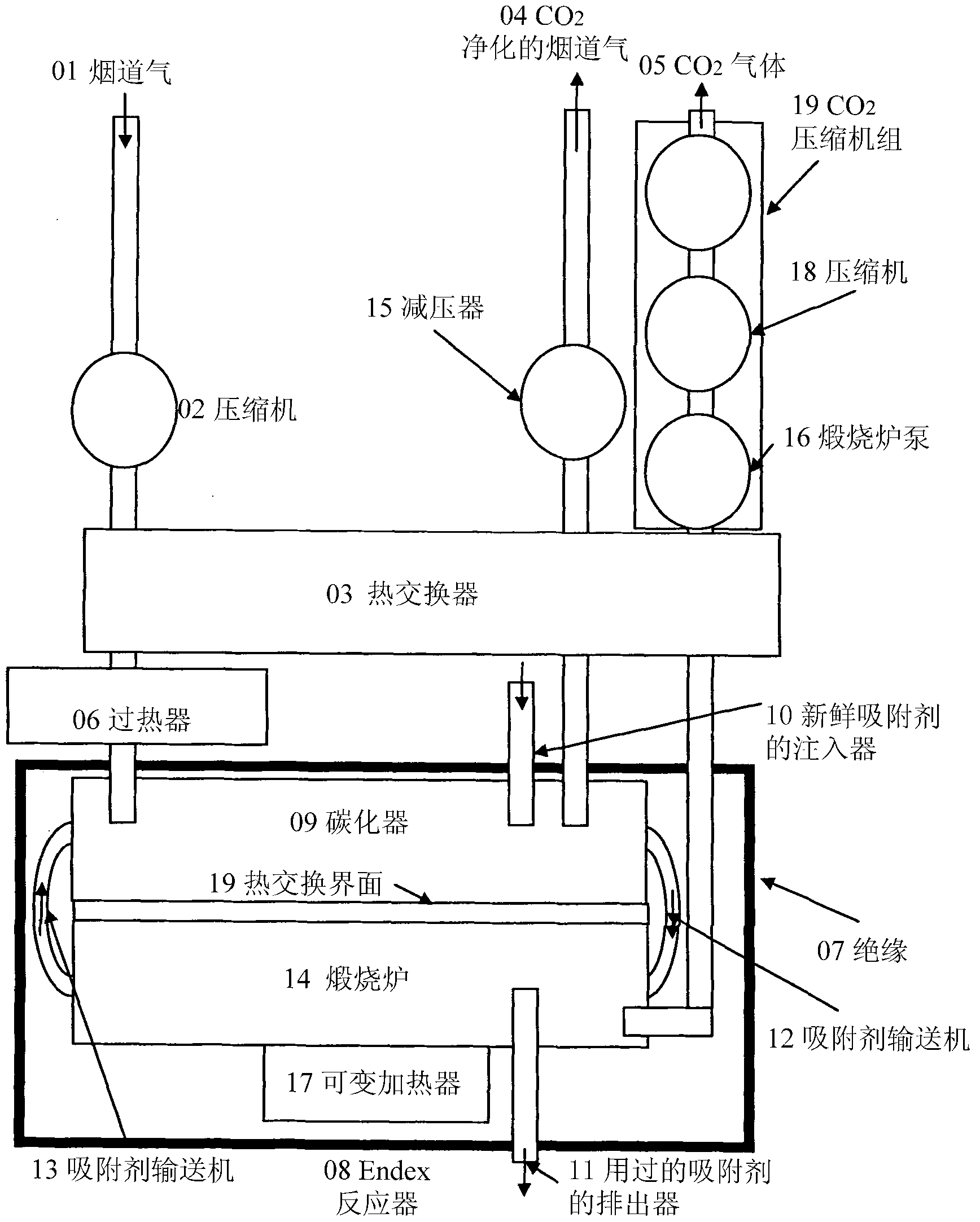
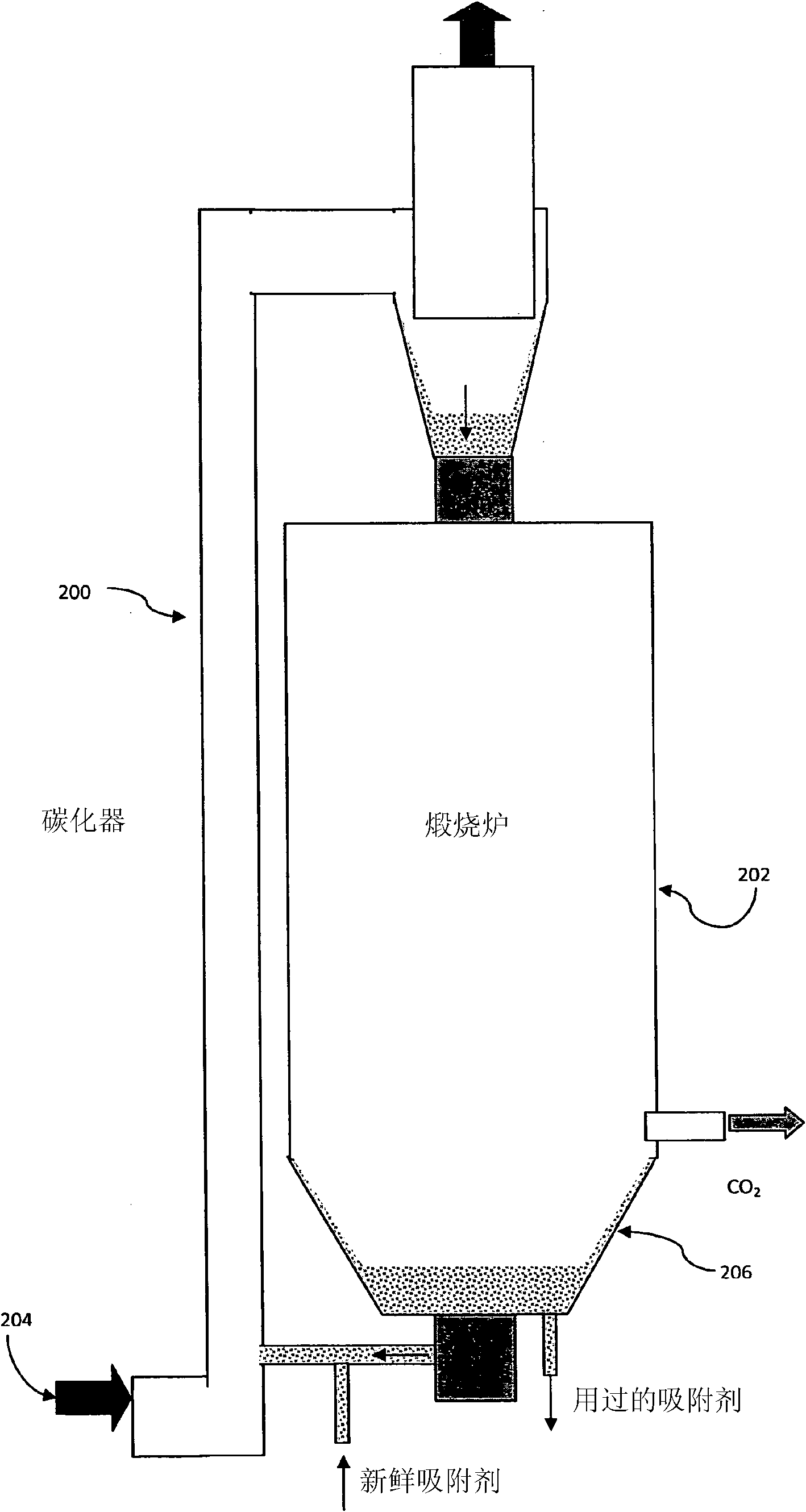
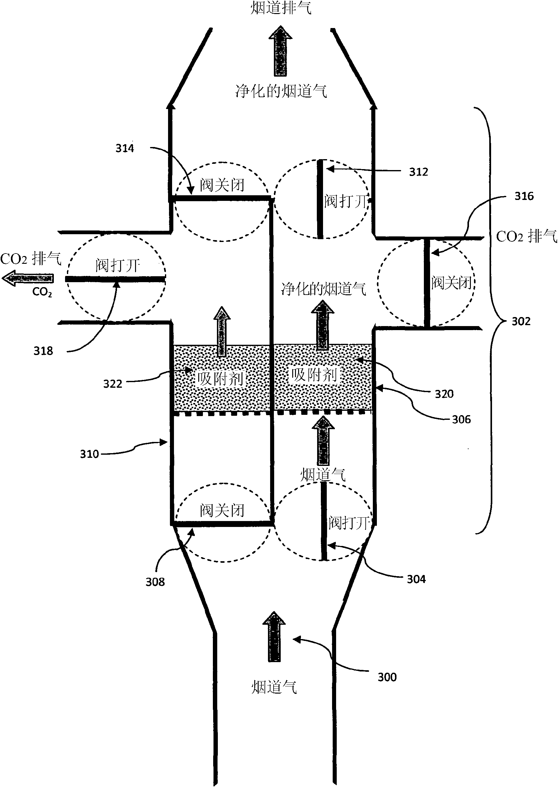
[0039] For the separation of carbon dioxide (CO2) from gas streams, such as flue gas or fuel gas 2 ) The exemplary system and method embodiments described use particles of a solid sorbent, such as lime. The system consists of: carbonizer reactor section with sorbent that extracts CO from the gas stream 2 ; the calciner reactor section, which converts CO 2 Release into (become a pure gas stream) and regenerate the sorbent; and means to allow heat to flow between them. The system is designed to reduce the net consumption of energy by setting the gas temperature and pressure in each section so that the carbonizer advantageously operates at a higher temperature than the calciner, and under these conditions it is possible to convert the CO adsorption in the carbonizer 2 The released heat is supplied to and consumed by the calciner to desorb (desorb) CO 2 . In an exemplary embodiment when CO in the calciner exhaust 2 Pressure lower than CO in the carbonator exhaust 2 When und...


PUM


Abstract

The invention relates to a system and a method for removing CO2 from an input gas stream. The system comprises a carboniser segment configured such that a solid sorbent reacts therein with the input gas stream to remove CO2 from the input gas stream; a calciner segment configured such that the solid sorbent from the carboniser segment reacts therein to release the CO2 into a substantially pure gas stream; a heat exchanger unit for exchanging heat between the carboniser and calciner segments; a first conditioning unit for controlling a CO2 partial pressure in the carboniser segment; and a second conditioning unit for controlling a CO2 partial pressure in the calciner segment; wherein the first and second conditioning units are configured such that a difference between the CO2 partial pressures in the carboniser and calciner segments respectively is controlled such that heat is provided from the carboniser to the calciner through the heat exchanging unit.

Description

technical field [0001] The present invention is primarily concerned with the removal of CO from input gas streams 2 systems and methods. Background technique [0002] There is a need for methods that can capture CO from flue or fuel gases produced by, for example, power plants, cement plants, and steel plants 2 , to mitigate the CO 2 Global warming caused by emissions. Separation of CO from gases such as flue gases produced in industrial processes 2 is the first step in a carbon capture and sequestration (CCS) process in which CO is separated 2 , compressed into a high-density fluid, transported and isolated (sequester) in deep saline aquifers, depleted oil and gas fields, deep coal seams, or deep sea reservoirs (reservoir). [0003] Due to the release of CO 2 There are very large investments associated with the existing industrial infrastructure, so preferably, the separation process can be modified to capture the flue gas exhausted from the above existing infrastruct...

Claims


Application Information

Patent Timeline
Patent Type & Authority Applications(China)
IPC IPC(8): B01D53/62B01D53/02B01D53/14B01D53/73C01B31/20C01B32/50
CPCY02C10/08B01D2259/40098B01D53/04B01D53/08Y02C10/06B01D2251/404B01D2251/606B01D53/346Y02C10/04B01D2259/128B01D53/62B01D2257/504B01D53/343B01D2259/65Y02C20/40
Inventor 马克·G·西茨
Owner CALIX PTY LTD
Why Eureka
Try Eureka