
Shape memory alloy spring-driven jumping robot

A memory alloy spring and robot technology, applied in the field of robots, can solve the problems of heavy structure, small power-to-weight ratio, and high driving voltage, and achieve the effects of simple structure, stable performance and improved bounce height.

Inactive Publication Date: 2012-10-17
NORTHEASTERN UNIV LIAONING
View PDF0 Cites 0 Cited by
  • Summary
  • Abstract
  • Description
  • Claims
  • Application Information

AI Technical Summary

Problems solved by technology

However, these two mobile robots have a common defect: it is difficult to jump over large obstacles or ditches at one time
[0003] Most commonly used robots are driven by servo motors, which have a small power-to-weight ratio and require a deceleration mechanism, which increases the size of the robot, has a heavy structure, and requires high precision parts; at the same time, the motor drive has noise and pollution, and the drive voltage is also high. , which is very unfavorable for the miniaturization of robots and the development of household and service industries

Method used


Image

  • Shape memory alloy spring-driven jumping robot
  • Shape memory alloy spring-driven jumping robot
  • Shape memory alloy spring-driven jumping robot

Examples


Embodiment 1

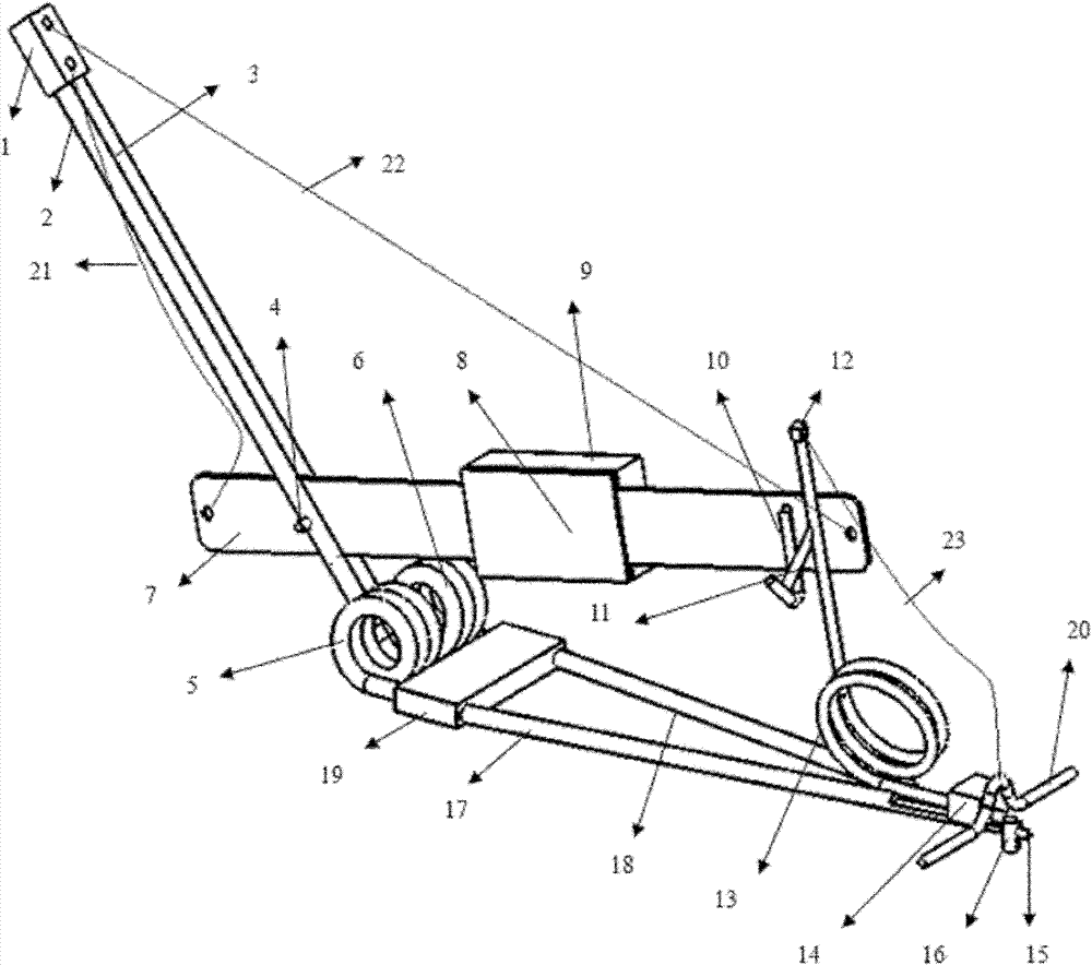
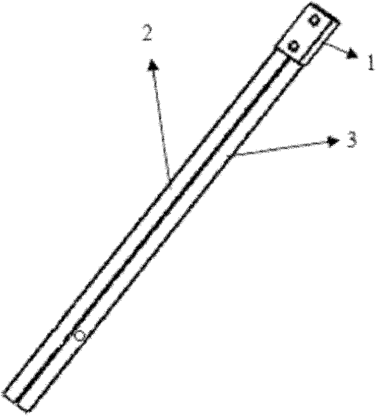
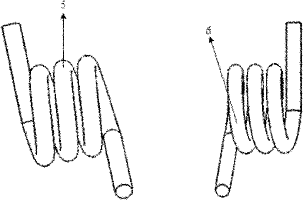
[0027] A bouncing robot driven by a shape memory alloy spring, comprising a forearm, an energy storage mechanism, an energy conversion mechanism, a rear arm, a trigger mechanism, a control system, a battery and an angle adjustment column; the forearm is composed of a first connecting block 1, a first rod 2 and The second rod 3 is fixedly connected, the first rod 2 and the second rod 3 are arranged in parallel and fixed on the first connecting block 1; the energy storage mechanism consists of a pair of first torsion springs arranged in parallel and symmetrically 5 and the second torsion spring 6, the front and rear extension ends of the two torsion springs are respectively inserted on the forearm and the rear arm; the energy conversion mechanism adopts a rotary lever type energy conversion mechanism, and the first memory alloy spring 21, the second The memory alloy spring 22, the third memory alloy spring 23, the rotary lever 7, the first hook 10 and the first bearing pin 4 are ...

Embodiment 2

[0029]A bouncing robot driven by a shape memory alloy spring, comprising a forearm, an energy storage mechanism, an energy conversion mechanism, a rear arm, a trigger mechanism, a control system, a battery and an angle adjustment column; the forearm is composed of a first connecting block 1, a first rod 2 and The second rod 3 is fixed, the first rod 2 and the second rod 3 are arranged in parallel and fixed on the first connecting block 1; the energy storage mechanism is composed of a pair of first torsion springs 5 ​​arranged in parallel and symmetrical Formed with the second torsion spring 6, the front and rear extension ends of the two torsion springs are respectively inserted on the forearm and the rear arm; the energy conversion mechanism adopts a slider type energy conversion mechanism, and the slider 24, the third memory alloy spring 23 , the fourth memory alloy spring 26, the fifth memory alloy spring 27, the first two-way memory alloy spring 28 and the fifth rod 25, the...

Embodiment 3

[0031] A bouncing robot driven by a shape memory alloy spring, comprising a forearm, an energy storage mechanism, an energy conversion mechanism, a rear arm, a trigger mechanism, a control system, a battery and an angle adjustment column; the forearm is composed of a first connecting block 1, a first rod 2 and The second rod 3 is fixed, the first rod 2 and the second rod 3 are arranged in parallel and fixed on the first connecting block 1; the energy storage mechanism is composed of a pair of first torsion springs 5 ​​arranged in parallel and symmetrical Formed with the second torsion spring 6, the front and rear extension ends of the two torsion springs are respectively inserted on the forearm and the rear arm; the energy conversion mechanism adopts a double spring type energy conversion mechanism, and the third memory alloy spring 23 and the second double The second two-way memory alloy spring 29 is connected between the first connection block 1 of the forearm and the second ...


PUM


Abstract

The invention relates to a shape memory alloy spring-driven jumping robot which comprises a front arm, an energy storage mechanism, an energy conversion mechanism, a rear arm, a trigger mechanism, a control system, a battery and an angle adjusting column, wherein the front arm is formed by fixedly connecting a first connection block, a first bar and a second bar; the energy storage mechanism comprises a pair of torsion springs which are coaxially and symmetrically arranged in parallel, or parallel two rows of torsion springs, or reeds symmetrically arranged in the horizontal direction; the front exposed end and the rear exposed end of the energy storage mechanism are inserted on the front arm and the rear arm; the rear arm is formed by fixedly connecting a second connection block, a thirdbar, a fourth bar and a third connection block; the trigger mechanism is formed by welding a trigger torsion spring, a second hanger and a fourth connection block, and is fixed at the rear part of the rear arm; the control system comprises a power supply part, a single chip microcomputer part and a driving part; and the angle adjusting column is connected at the tail end of the rear arm through apin shaft. The jumping robot has a simple structure and stable performances, and overcomes the disadvantages in the prior art that the power-to-weight ratio is small, the noise and the pollution are generated during driving and the driving voltage is higher.

Description

technical field [0001] The invention belongs to the technical field of robots, in particular to a bouncing robot driven by a shape memory alloy spring. Background technique [0002] At present, mobile robots mainly adopt two locomotion modes: multi-wheel or crawler drive, bionic crawling or walking. However, these two mobile robots have a common defect: it is difficult to jump over larger obstacles or ditches at one time. With the increasingly wide application range of robots, the working environment faced by robots is getting worse and worse, such as archaeological exploration, military reconnaissance, anti-terrorism activities, etc. In such an environment, it is obvious that robots must have strong terrain adaptation and autonomous movement capabilities . Compared with the above two mobile robots, the bouncing robot can successfully jump over obstacles several times higher than its own size. For example, the 7-gram bouncing robot studied by the University of Lausanne in ...

Claims


Application Information

Patent Timeline
Patent Type & Authority Patents(China)
IPC IPC(8): B62D57/04
Inventor 郭江龙陈述平李龙袁忠秋石祎元刘天琦窦志龙张青春刘淳
Owner NORTHEASTERN UNIV LIAONING
Learn More