Laser scanning method for selective laser firing

A technology of laser sintering and laser scanning, which is applied in the field of laser scanning, can solve the problems of not proposing a better solution, increasing the cost of equipment and process, and increasing the difficulty of the system, so as to reduce the number of filling scans, improve the accuracy, and improve the scanning efficiency Effect

Inactive Publication Date: 2011-07-06
许小曙
View PDF7 Cites 18 Cited by
  • Summary
  • Abstract
  • Description
  • Claims
  • Application Information

AI Technical Summary

Problems solved by technology

Filling scanning is mainly a straight line scanning of the laser beam along the x / y axis, and the shrinkage stress direction of adjacent scanning lines is opposite, which can reduce the influence of the overall stress on the workpiece; there is also a circular scanning method from the inside to the outside. Carry out cross-section filling scanning, but the scanning speed of this method is relatively slow; some studies further use a composite scanning method combining contour circular scanning and partition-changing scanning to ensure the accuracy of the workpiece, but the process control is more complicated
In order to further improve the scanning speed, the variable spot scanning method can be adopted, that is, the contour scanning of the section is carried out with a small spot to fully ensure the accuracy of the workpiece, and the spot is enlarged through the movement of dynamic aggregation, and the section is filled and scanned to increase the scanning distance. , to increase the scanning speed, but this method must be realized through complex hardware system adjustments, which increases the difficulty of the system and increases the cost of equipment and processes
On the problem of shrinkage deformation, the prior art has not yet proposed a better solution

Method used


Image

  • Laser scanning method for selective laser firing
  • Laser scanning method for selective laser firing
  • Laser scanning method for selective laser firing

Examples


Embodiment 1

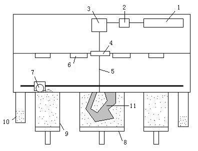
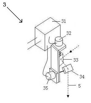
[0028] The equipment that the inventive method adopts is as figure 1As shown, in the SLS equipment, the powder feeding device 9 sends a certain amount of powder to the worktable, and after the powder is preheated, the powder spreading roller 7 evenly spreads the powder on the upper surface of the molded part 11 in the working cylinder 8 , the excess powder is recovered to the overflow powder cylinder 10, the heating device 6 heats the laid powder to a temperature just below the sintering point of the powder, the laser beam 5 emitted from the laser 1 is reflected by the prism 2 to the vibrating mirror system 3, and vibrates The mirror system 3 controls the laser beam 5 to pass through the laser window 4 to the working table for filling and scanning sintering of the cross-section powder of the workpiece 11 . The laser galvanometer system in SLS equipment 3 such as figure 2 As shown, two vibrating mirrors are included: x-axis vibrating mirror 33 and y-axis vibrating mirror 34, ...

Embodiment 2

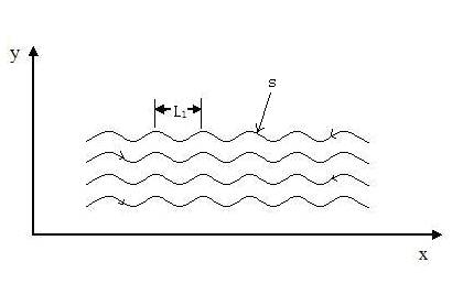
[0030] In this embodiment, the filling scanning path s of the laser beam is a spiral regular curve, and during a single scanning process of the spiral filling scanning, both the x-axis vibrating mirror and the y-axis vibrating mirror need to alternately swing in positive and negative directions. like Figure 4 As shown, the laser beam fills, scans and sinters the cross-section of the workpiece from the starting position according to the spiral scanning path, the galvanometer system controls the position of the laser beam, the scanning line waveform changes periodically, and the pitch L 2 1mm~5mm. For the first time, the overall scanning line grows spirally along the +x direction. When scanning to point a of the spiral coil, the growth direction of the scanning line changes to the -x direction, and when scanning to the point b of the spiral coil, the growth direction of the scanning line on the x-axis changes to +x direction, several changes in the x-axis direction will occur ...

Embodiment 1、2

[0031] In addition to Embodiments 1 and 2, the method of the present invention can also control the filling scanning path of the laser beam to be a curve of any shape as required.


PUM


Abstract

The invention discloses a laser scanning method for selective laser firing, wherein the cross section of prepared parts is supplementarily scanned by using laser beams in the process of selective laser firing. The supplementary scanning path of the laser beam is curve, interrupted curve or interrupted straight line. The method is convenient in process, has strong practicability, and plays an important role in reducing the buckling deformation of parts and increasing the parts precision.

Description

technical field [0001] The invention belongs to a laser scanning method, in particular to a laser scanning method used in selective laser sintering technology. Background technique [0002] Rapid Prototyping (RP) is an advanced manufacturing technology with distinctive features such as digital manufacturing, high flexibility and adaptability, direct CAD model drive, fast speed, and rich and diverse material types. Since the late 1980s, So far, it has become a pillar technology in modern advanced manufacturing technology. Selective Laser Sintering (SLS) is one of the fastest-growing rapid prototyping technologies in recent years. It uses powder materials as raw materials and uses laser to scan the cross-section of three-dimensional solid parts layer by layer to complete the original prototype manufacturing. It is not limited by the complexity of the shape of the parts, does not require any tooling and molds, and has a wide range of applications. The basic process of the SLS...

Claims


Application Information

Patent Timeline
IPC IPC(8): G02B26/10C23C24/10
Inventor 许小曙
Owner 许小曙
Why Eureka
Try Eureka