Device and method for monitoring abnormal state of light-emitting diode

A light-emitting diode, abnormal state technology, applied in lighting devices, light sources, electric light sources, etc., can solve problems such as increased use costs, inability to guarantee photosensitive devices, failure detection, etc., to facilitate maintenance and replacement, ensure curing quality, and ensure normal effect of work

Inactive Publication Date: 2011-07-06
PEKING UNIV FOUNDER GRP CO LTD +2
View PDF1 Cites 16 Cited by
  • Summary
  • Abstract
  • Description
  • Claims
  • Application Information

AI Technical Summary

Problems solved by technology

Due to its structural characteristics, the tubular high-pressure mercury lamp has the following disadvantages in the use of ultraviolet curing technology: that is, in the length direction of the mercury lamp, the luminous intensity at both ends is weak, and an irradiation area with uniform intensity cannot be formed. The curing effect is reduced; the high-pressure mercury lamp is a thermal light source, and the temperature of the tube wall is usually 600 to 800 degrees Celsius, and the corresponding cooling device is large in size, resulting in high cost; because the high-pressure mercury lamp is a thermal light source, it will generate a lot of infrared rays. It is not suitable for materials that are sensitive to heat, and the generation efficiency of ultraviolet rays is low; in addition, the life of high-pressure mercury lamps is relatively low, generally only 1 to 2,000 hours, and the lamp tube needs to be replaced frequently, which will also cause Increase the cost of use
However, the disclosed technical solution of this patent has the following defects: since the photosensitive device can only be arranged in the vicinity of the LED to be tested at a short distance, and the current changes according to the intensity of the received light source, when the dense setting encountered by the present invention When there are multiple light-emitting diodes in the light-emitting diode array, it cannot be guaranteed that the light source received by the photosensitive device is the light source emitted by the corresponding LED device, so the technical solution proposed by this patent cannot solve the technical problem of the present invention
[0007] In addition, based on safety considerations, it is not possible to perform manual inspection of ultraviolet lamps under working conditions.
Therefore, based on the above-mentioned phenomenon in the prior art, it is urgent to solve the problem of how to monitor and fail to detect the working status of each LED in the UV curing lamp using the UV LED array in real time.

Method used


Image

  • Device and method for monitoring abnormal state of light-emitting diode
  • Device and method for monitoring abnormal state of light-emitting diode
  • Device and method for monitoring abnormal state of light-emitting diode

Examples


Embodiment 1

[0029] When monitoring the state of a light-emitting diode, the implementation technical solution of the present invention adopts the following settings.

[0030] The set monitoring device includes a circuit module; a first reference voltage source, which generates a first reference voltage VL, as the low threshold VL of the light-emitting diode operating voltage; a second reference voltage source, which generates a second reference voltage VH, as a light-emitting diode A high threshold VH of the working voltage; wherein, both the low threshold VL and the high threshold VH of the light emitting diode working voltage are transmitted to the circuit module.

[0031] The circuit module of the present invention includes: a subtractor, which is connected in parallel at both ends of the light-emitting diode, and is used to generate the working voltage VF of the light-emitting diode; the subtractor is connected with a first comparator and a second comparator, wherein the first A compa...

Embodiment 2

[0034] In the case of multiple light emitting diodes on the circuit, the present invention also provides a device for monitoring the abnormal state of each light emitting diode. Referring now to the accompanying drawings, the specific structural features of this embodiment will be described in detail.

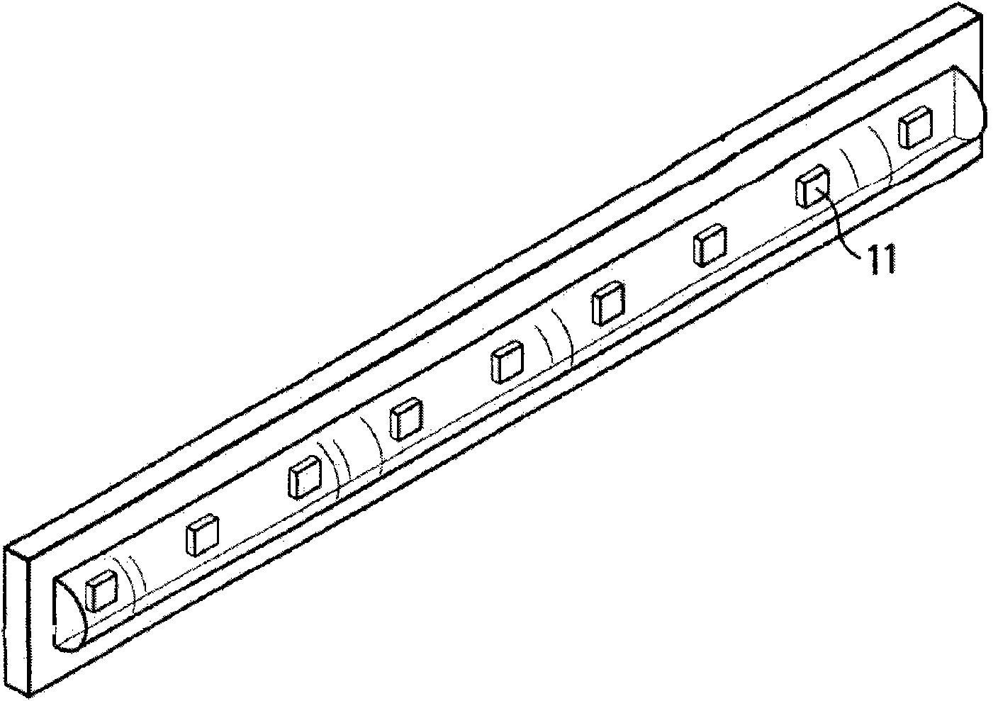
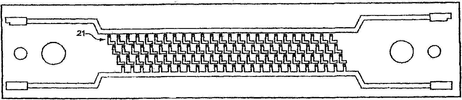
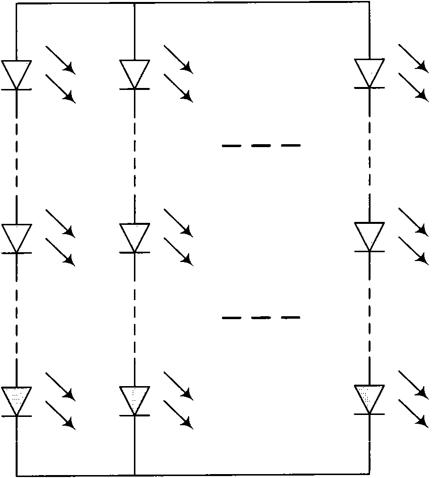
[0035] figure 1 and figure 2 An ultraviolet curing lamp composed of two ultraviolet light emitting diode arrays in the prior art is shown. exist figure 1 and figure 2 Among them, the light-emitting diodes 11 and 21 are different types of high-power ultraviolet light-emitting diodes installed on the base plate respectively, and a plurality of light-emitting diodes 11 and 21 form a light-emitting diode array, thereby obtaining high-power ultraviolet light output. image 3 It is a schematic diagram of a driving mode of light emitting diodes connected in series first and then in parallel in the prior art.

[0036] In order to facilitate understanding of the inventive concept...


PUM


Abstract

The invention relates to a device and method for monitoring the abnormal state of a light-emitting diode. The device is connected to both ends of the light-emitting diode and can be used for monitoring the abnormal state of the light-emitting diode by detecting the change of the working voltage of the light-emitting diode. The device and the method can be used for monitoring the working voltage VF of each light-emitting diode in a light-emitting diode matrix in real time, judging whether the working voltage VF is higher than a determined high threshold voltage VH or not and whether the working voltage VF is lower than a determined low threshold voltage VL or not, and accordingly judging whether a current light-emitting diode abnormally works or not, or short circuit or open circuit faults are already generated or not; and in addition, the positions of the light-emitting diodes which abnormally work and go wrong can be positioned quickly under the working state of the light-emitting diode matrix so as to facilitate maintenance and replacement.

Description

technical field [0001] The invention relates to the field of circuit detection, and more specifically, the invention relates to a device and method for monitoring the abnormal state of a light emitting diode. Background technique [0002] In the traditional UV curing technology, the commonly used UV light sources are mostly tubular high-pressure mercury lamps. Due to its structural characteristics, the tubular high-pressure mercury lamp has the following disadvantages in the use of ultraviolet curing technology: that is, in the length direction of the mercury lamp, the luminous intensity at both ends is weak, and an irradiation area with uniform intensity cannot be formed. The curing effect is reduced; the high-pressure mercury lamp is a thermal light source, and the temperature of the tube wall is usually 600 to 800 degrees Celsius, and the corresponding cooling device is large in size, resulting in high cost; because the high-pressure mercury lamp is a thermal light source...

Claims


Application Information

Patent Timeline
Patent Type & Authority Applications(China)
IPC IPC(8): H05B37/03
Inventor 俞建国陈峰刘志红
Owner PEKING UNIV FOUNDER GRP CO LTD
Why Eureka
Try Eureka