Tire and wheel noise reducing device and system

A tire and wheel technology, applied in the field of sound reduction devices, can solve the problems of inability to reduce low-frequency energy noise, hindering tire inflation, safety accidents, etc.

Inactive Publication Date: 2011-07-06
TIRE ACOUSTICS LLC
View PDF4 Cites 8 Cited by
  • Summary
  • Abstract
  • Description
  • Claims
  • Application Information

AI Technical Summary

Problems solved by technology

In particular, those methods do not effectively absorb the low frequency energy (e.g., below 800 Hz) associated with the shock waves that generate tire noise
While tires generate considerable low frequency energy, an effective tire noise absorber should reduce the noise generated by this low frequency energy, however, conventional methods do not adequately reduce this noise
In addition, low frequency noise amplifies the perceived high frequency noise generated by tread air compression and tire scuffing, thus conventional methods cannot reduce perceived high frequency tire noise due to their inability to reduce low frequ

Method used


Image

  • Tire and wheel noise reducing device and system
  • Tire and wheel noise reducing device and system
  • Tire and wheel noise reducing device and system

Examples


Embodiment Construction

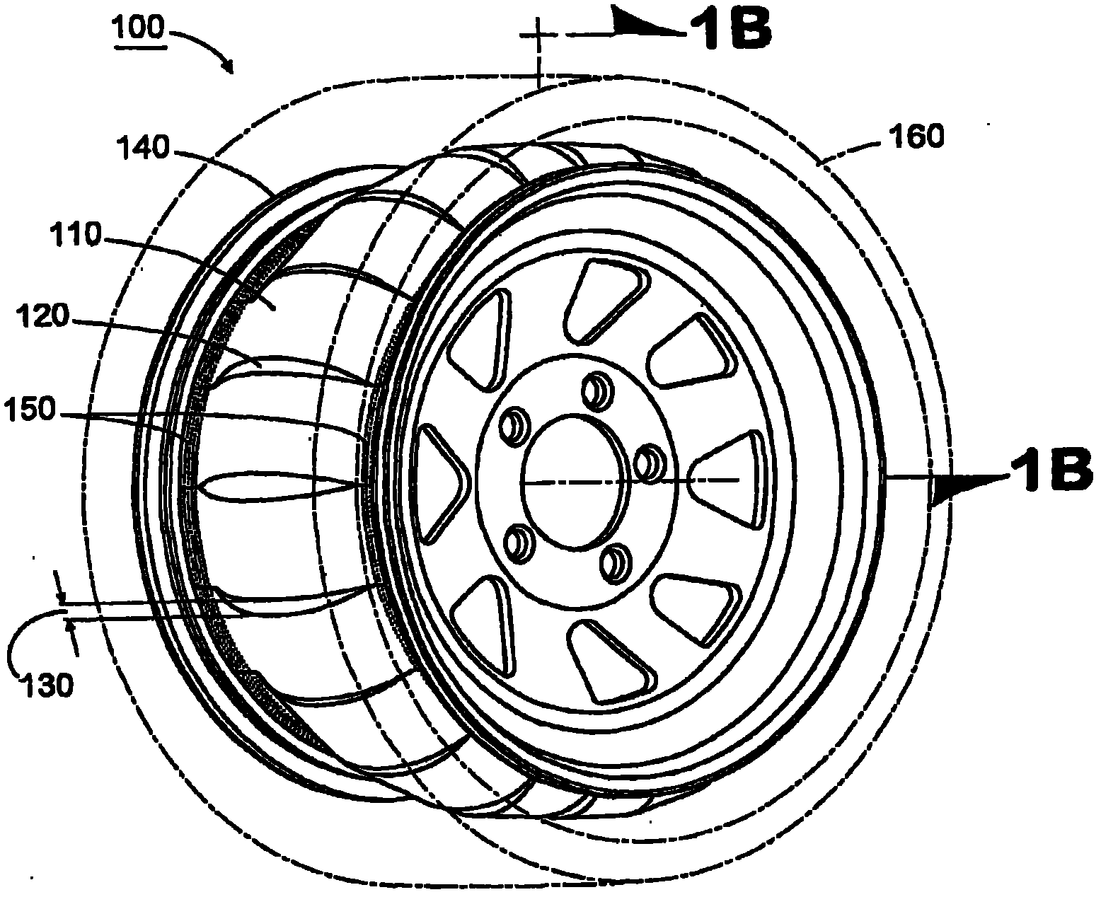
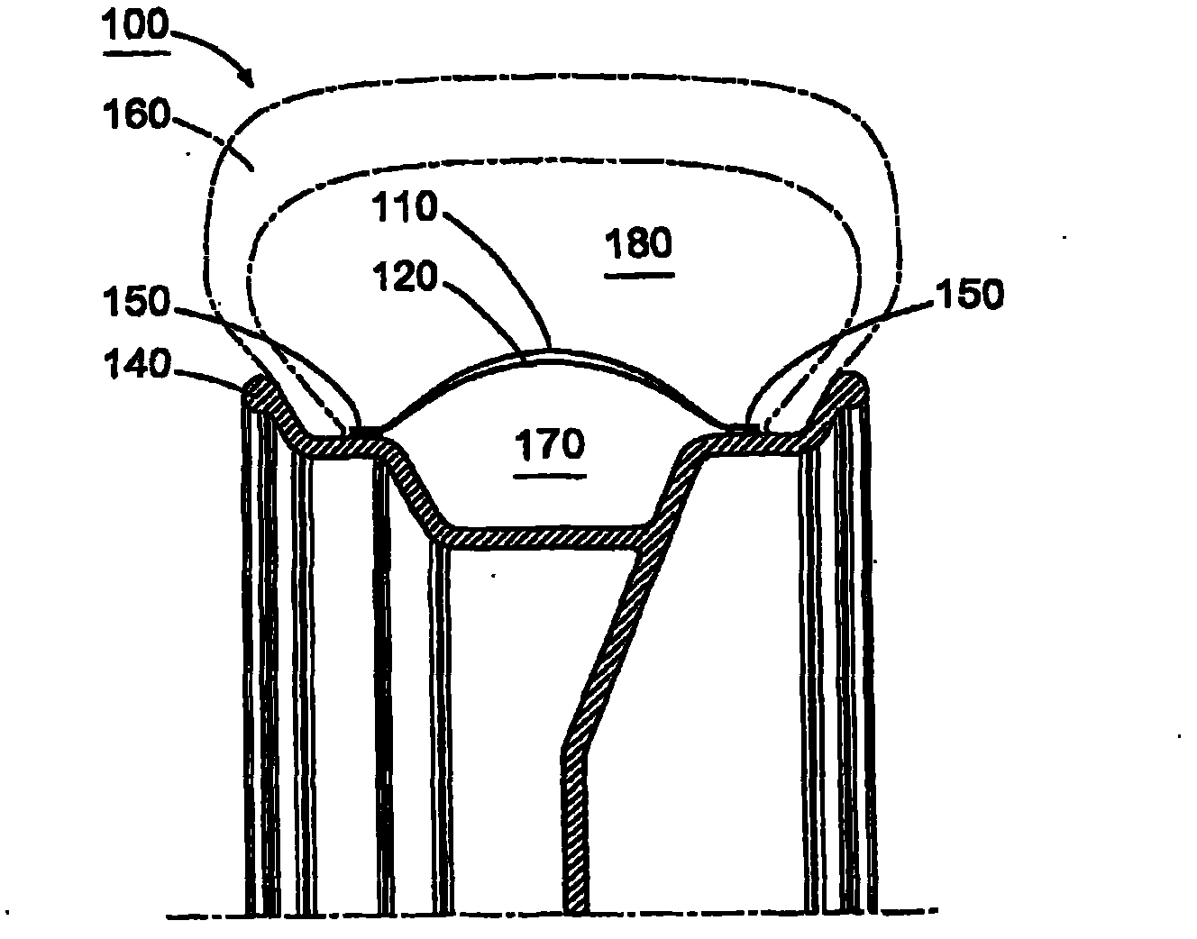
[0042] Exemplary embodiments are described below with reference to FIGS. 1-13 , wherein like reference numerals indicate similar elements.

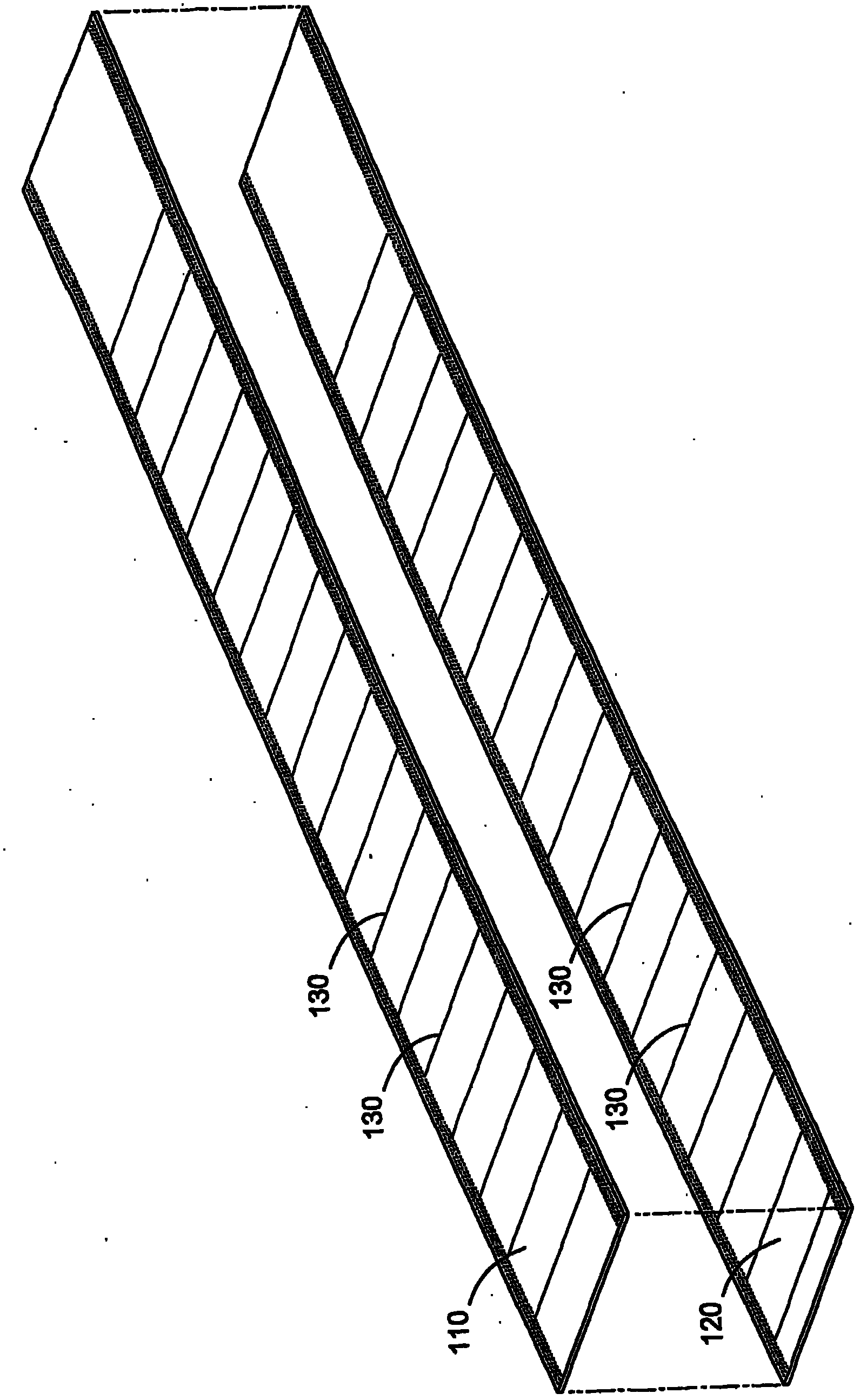
[0043] Figure 1A is a perspective view showing a tire noise absorbing system 100 including a flow blocking barrier disposed on a wheel 140 for a tire 160 according to an exemplary embodiment. Figure 1B yes Figure 1A A cross-sectional view of the exemplary system 100 shown in . Such as Figure 1A and 1B As shown in , the system 100 includes a plurality of overlapping material layers 110, 120 that form a sound-related flow-resistant barrier. Layer 110 includes an outer layer with respect to wheel 140 and layer 120 includes an inner layer with respect to wheel 140 . The overlapping layers 110, 120 are joined to the wheel 140 at locations 150 along their edges to form overlapping loops of material. In other words, layers 110 , 120 surround wheel 140 and are bonded to both sides of wheel 140 at location 150 . Location 150 represents any...


PUM


Abstract

A system for dissipating sound shock waves within a vehicle tire includes a wheel upon which a tire is mounted to create an internal air chamber defined by the wheel and the tire. A flow-resistant barrier is coupled to the wheel or the tire and defines an air cavity within the internal air chamber. A porous spacer can support the barrier with respect to the tire and also can provide a flexible energy damper. The barrier comprises a material that provides an acoustical resistance to sound shock waves passing therethrough. The air cavity defined by the barrier has a volume such that air within the cavity offers relatively small impedance to the passage of shock waves through the barrier and into the air cavity. The barrier also can produce frictional heat when displaced by a shock wave, thereby converting energy of the shock wave to heat to reduce noise associated therevvith.

Description

[0001] related application [0002] This patent application claims priority under 35 U.S.C. §120 to U.S. Patent Application No. 11 / 473,928, filed June 23, 2006, entitled "Tire and Wheel Noise Reduction Apparatus and System," which is filed under 35 U.S.C. §119 claims priority to US Provisional Patent Application No. 60 / 694,018, filed June 24, 2005, entitled "Tire and Wheel Noise Absorbing Apparatus and Systems." The entire disclosure of each of the above-identified priority applications is hereby incorporated by reference in its entirety. technical field [0003] The present invention relates generally to reducing vehicle noise from tires and wheels, and more particularly, the present invention relates to a sound reducing device disposed within an internal air chamber formed by the tire and the wheel on which the tire is mounted. Background of the invention [0004] When car tires hit the road, they make quite a bit of noise. In some vehicles, at speeds above 25 mph, tire ...

Claims


Application Information

Patent Timeline
IPC IPC(8): B60C5/00B60C17/04B60C19/00B60B19/00
CPCB60B2310/318B60C5/22B60Y2200/11B60B1/06B60B2900/133B60B2360/3418B60B21/12B60C5/20B60B2310/306B60C19/002B60B2310/302B60B2360/3412Y10T152/10522B60C19/00E04B1/8409
Inventor S·E·福勒-霍金斯
Owner TIRE ACOUSTICS LLC
Why Eureka
Try Eureka