Steam turbine condenser exhaust pipe

A technology of condenser and steam turbine, applied in steam/steam condensers, lighting and heating equipment, etc., can solve the problems of limited number of exhaust pipes and small volume ratio of exhaust pipes, and achieve small flow resistance, uniform heat load, The effect of improving the heat transfer coefficient

Active Publication Date: 2015-07-29
DONGFANG TURBINE CO LTD
View PDF4 Cites 0 Cited by
  • Summary
  • Abstract
  • Description
  • Claims
  • Application Information

AI Technical Summary

Problems solved by technology

Due to the limitation of its slender structure, the BD modular pipe row has a very limited number of pipes under the condition of a certain size of the tube sheet, which makes the volume ratio of the pipe row small, and is not suitable for nuclear power steam turbines and other occasions.

Method used


Image

  • Steam turbine condenser exhaust pipe
  • Steam turbine condenser exhaust pipe
  • Steam turbine condenser exhaust pipe

Examples


Embodiment Construction

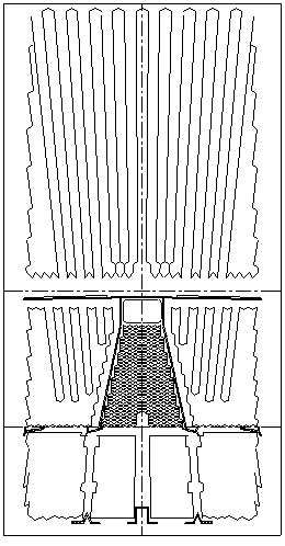
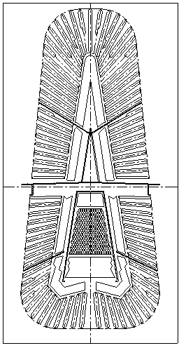
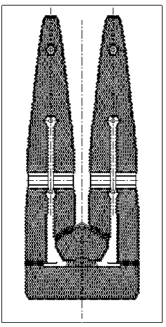
[0021] Such as Figure 4 As shown, the present invention is a row pipe of a steam turbine condenser. The row pipes are a plurality of cooling pipes 19 with uniform spacing and parallel axes. The cooling pipes 19 constitute two independent pipe-containing areas, the air cooling zone 14 and the main condensation zone. The main condensation zone is arranged around the air cooling zone 14.

[0022] Condenser exhaust pipe of the present invention, has designed a kind of new arrangement mode of condenser cooling tube bundle: the outline shape of the projection of the envelope line of its tube-containing area on the plane perpendicular to the axis of cooling tube 19 is torch-like , that is, the cross-sectional profile of the tube-containing area perpendicular to the axis of the cooling tube 19 is a symmetrical torch shape, and the projection plane (section) is parallel to the condenser end tube plate 21. The air cooling zone 14 is arranged at the middle and lower part of the "torch"...


PUM


Abstract

The invention provides a tube tank of a turbine condenser. The tube tank comprises multiple cooling tubes with parallel axes, and a tube containing area with two mutually independent tube areas, namely an air cooling area and a main condensation area, wherein the main condensation area is arranged around the air cooling area; the projection of an envelope curve of the tube containing area on a plane vertical to the axes of the cooling tubes forms a 'torch'-shaped pattern; the air cooling area is arranged at the middle lower part of the 'torch'; the tube tank of the main condensation area forms multiple 'flames' which are bilaterally symmetrical relative to the centre line of the 'torch' and called as trunk tube bundles of the tube tank of the condenser; and a clearance exists between adjacent trunk tube bundles in the width direction of the 'torch', and forms a steam channel. Through the invention, the heat exchange performance of the condenser is enhanced so that the condenser technology is further improved; and the applicable range of the tube tank of the condenser is expanded, and the tube tanks can be used as the tube tanks of condensers configured in the turbine units of various power levels, particularly to the nuclear power condensers with unit power over the million-kilowatt level.

Description

technical field [0001] The invention relates to the field of cooling tube bundle arrangement methods of condensers, in particular to a condenser tube arrangement method suitable for configurations of steam turbine units of various power levels. Background technique [0002] At present, the condensers of domestic and foreign power station steam turbines are designed and manufactured by their manufacturers, and the condenser tube bundles are arranged in different styles. [0003] In the last century, the condenser of the domestic three-exhaust steam 200MW unit adopted the peripheral strip type (see figure 1 ), oval ducts (see figure 2 ), due to the early design, using the technical achievements in the early 1950s, relatively backward. Compared with domestic experiments, the overall heat transfer coefficient of the egg-shaped row tube is higher than that of the peripheral belt-shaped tube, which is relatively better. However, according to the water model test of egg-shaped ...

Claims


Application Information

Patent Timeline
Patent Type & Authority Patents(China)
IPC IPC(8): F28B1/06
Inventor 张水桃刘伟龙鲁前奎许晔周进陈建徐成勇
Owner DONGFANG TURBINE CO LTD
Why Eureka
Try Eureka