Double-layer threaded turbulent flow heat exchanger

A technology of heat exchanger and thread, which is applied in the field of double-layer thread spoiler heat exchanger, can solve the problems of high manufacturing cost, unsatisfactory heat exchange efficiency, low pressure bearing capacity of heat exchanger, etc. Low cost, low cost, and improved heat utilization efficiency

Active Publication Date: 2011-07-13
广东百思特管业科技有限公司
View PDF6 Cites 7 Cited by
  • Summary
  • Abstract
  • Description
  • Claims
  • Application Information

AI Technical Summary

Problems solved by technology

At present, the common heat exchangers for heat pump water heating equipment on the market include plate heat exchangers, double-layer casing heat exchangers, shell-and-tube heat exchangers, shell-and-tube heat exchangers, etc. These common heat exchangers, The structure is relatively complex, the use cost and product manufacturing cost are relatively high, the heat exchange efficiency is not ideal, and the failure rate of the equipment is also high; moreover, these heat exchangers have low pressure bearing capacity and are not suitable for use in high-temperature environments. Pressure heat exchange equipment, such as heat pump hot water equipment using carbon dioxide compressors; in addition, plate heat exchangers are brazed with copper, while other heat exchangers use copper tubes for heat exchange in order to improve heat exchange efficiency, which avoids It will not be corroded and perforated, so that the equipment will be scrapped

Method used


Image

  • Double-layer threaded turbulent flow heat exchanger
  • Double-layer threaded turbulent flow heat exchanger
  • Double-layer threaded turbulent flow heat exchanger

Examples


Embodiment Construction

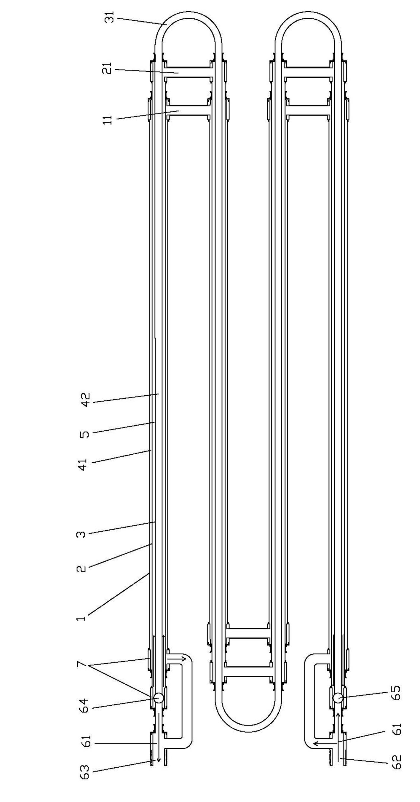
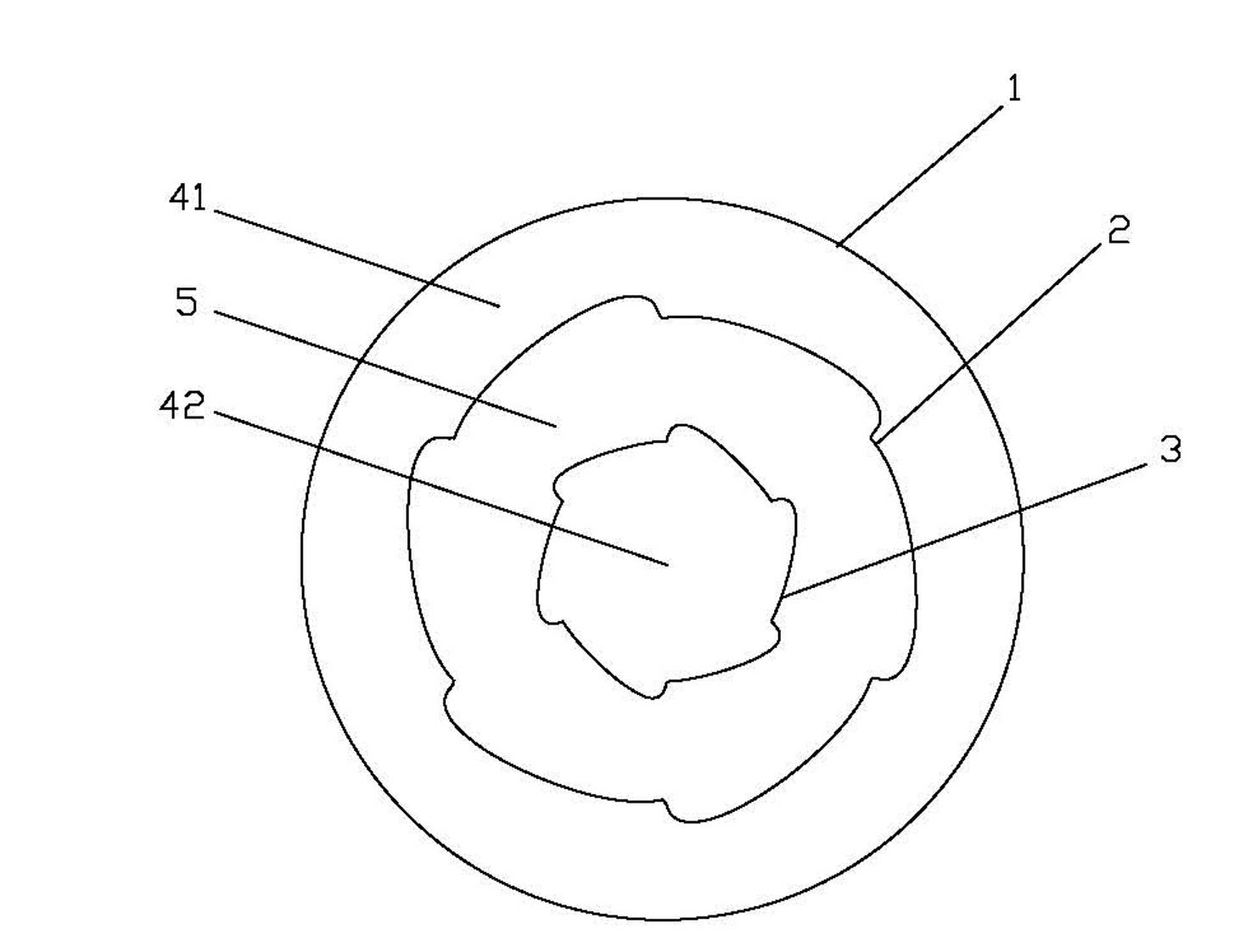
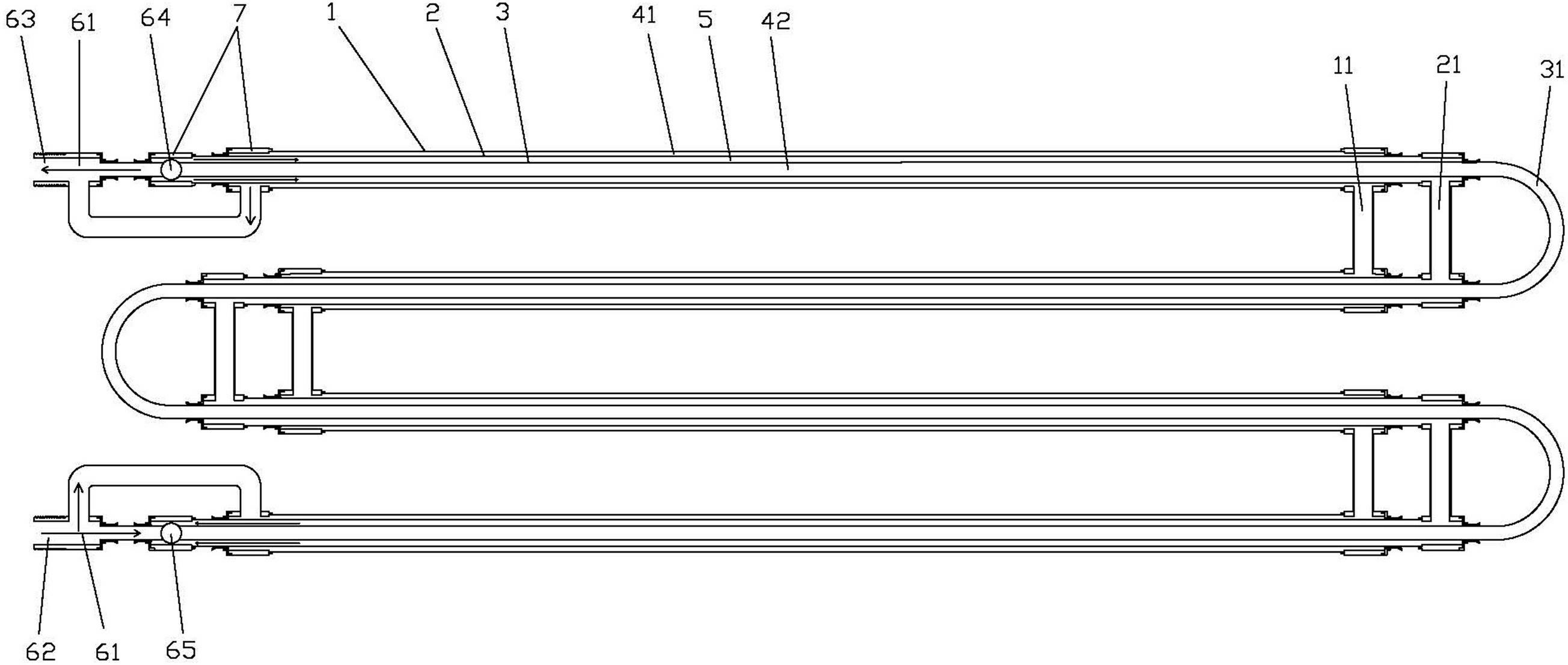
[0021] Such as figure 1 As shown, a double-layer threaded turbulent heat exchanger provided by the present invention includes a coaxial large pipe 1, a middle pipe 2 and a small pipe 3 that are nested together, and the large pipe 1, the middle pipe 2 and the small pipe 3 The stainless steel structure can be connected and fixed through the pipeline connector 7, and the pipeline connector 7 and each pipeline can be welded by argon arc welding or brazing.

[0022] In the present invention, the first cold medium passage 41 is formed between the large pipe 1 and the middle pipe 2, the heat medium passage 5 is formed between the middle pipe 2 and the small pipe 3, and the second cold medium passage 42 is formed in the small pipe 3; thus, Three passages are formed, among which the heat medium passage 5 is used to circulate the heat medium, the first cold medium passage 41 and the second cold medium passage 42 are used to circulate the cold medium, and the heat medium passage 5 is loc...


PUM


Abstract

The invention discloses a double-layer threaded turbulent flow heat exchanger which comprises a big pipe, a medium pipe and a small pipe, wherein the big, medium and small pipes are coaxial and sleeved with one another; a first cold medium channel is formed between the big pipe and the medium pipe; a hot medium channel is formed between the medium pipe and the small pipe; a second cold medium channel is formed in the small pipe; the medium and small pipes are threaded turbulent flow pipes; and the big pipe is a smooth pipe or threaded turbulent flow pipe. The heat exchanger provided by the invention can resist chloride ion corrosion and ensure the service life of equipment; the structure of a stainless steel three-layer threaded pipe ensures entirely uniform heat exchange and can prevent the formation of cold bridge and dirt in the pipe to ensure the heat exchange efficiency; and moreover, as a strong turbulent flow can be produced, heat exchange between the medium close to the pipe wall and the medium at the pipe center can be accelerated, thereby ensuring thorough heat exchange, improving equipment efficiency and prolonging the service life; and the sleeve structure has strong pressure bearing capacity, prevents influence on the equipment caused by excessively high pressure, pressure leakage failure and other factors during the operation of the equipment, and prolongs the service life.

Description

technical field [0001] The invention relates to heat pump water heating equipment, in particular to a double-layer screw thread turbulence heat exchanger applied to heat pump water heating equipment. Background technique [0002] Heat pump water heating equipment can obtain high heat energy by inputting a small amount of electric energy. It is a very effective hot water supply equipment. It uses heat-absorbing working fluid to absorb environmental heat, and transfers the absorbed heat to water through a heat exchanger. , to heat the water. At present, the common heat exchangers for heat pump water heating equipment on the market include plate heat exchangers, double-layer casing heat exchangers, shell-and-tube heat exchangers, shell-and-tube heat exchangers, etc. These common heat exchangers, The structure is relatively complex, the use cost and product manufacturing cost are relatively high, the heat exchange efficiency is not ideal, and the failure rate of the equipment i...

Claims


Application Information

Patent Timeline
Patent Type & Authority Applications(China)
IPC IPC(8): F28D7/00F28F1/08F28F21/08
Inventor 刘毅
Owner 广东百思特管业科技有限公司
Why Eureka
Try Eureka