Optical deflecting device

A light deflection device and ordinary light technology, applied in optics, nonlinear optics, instruments, etc.

Active Publication Date: 2011-07-13
STANLEY ELECTRIC CO LTD
View PDF7 Cites 7 Cited by
  • Summary
  • Abstract
  • Description
  • Claims
  • Application Information

AI Technical Summary

Problems solved by technology

However, in the technique disclosed in Japanese Patent Application Laid-Open No. 2006-147377, only one of the two polarization components whose polarization directions are orthogonal to each other in the incident light entering the liquid crystal cell is deflected.

Method used


Image

  • Optical deflecting device
  • Optical deflecting device
  • Optical deflecting device

Examples


Embodiment Construction

[0022] First, the structure and manufacturing method of the light deflecting liquid crystal cell described in the first embodiment of the present invention will be described.

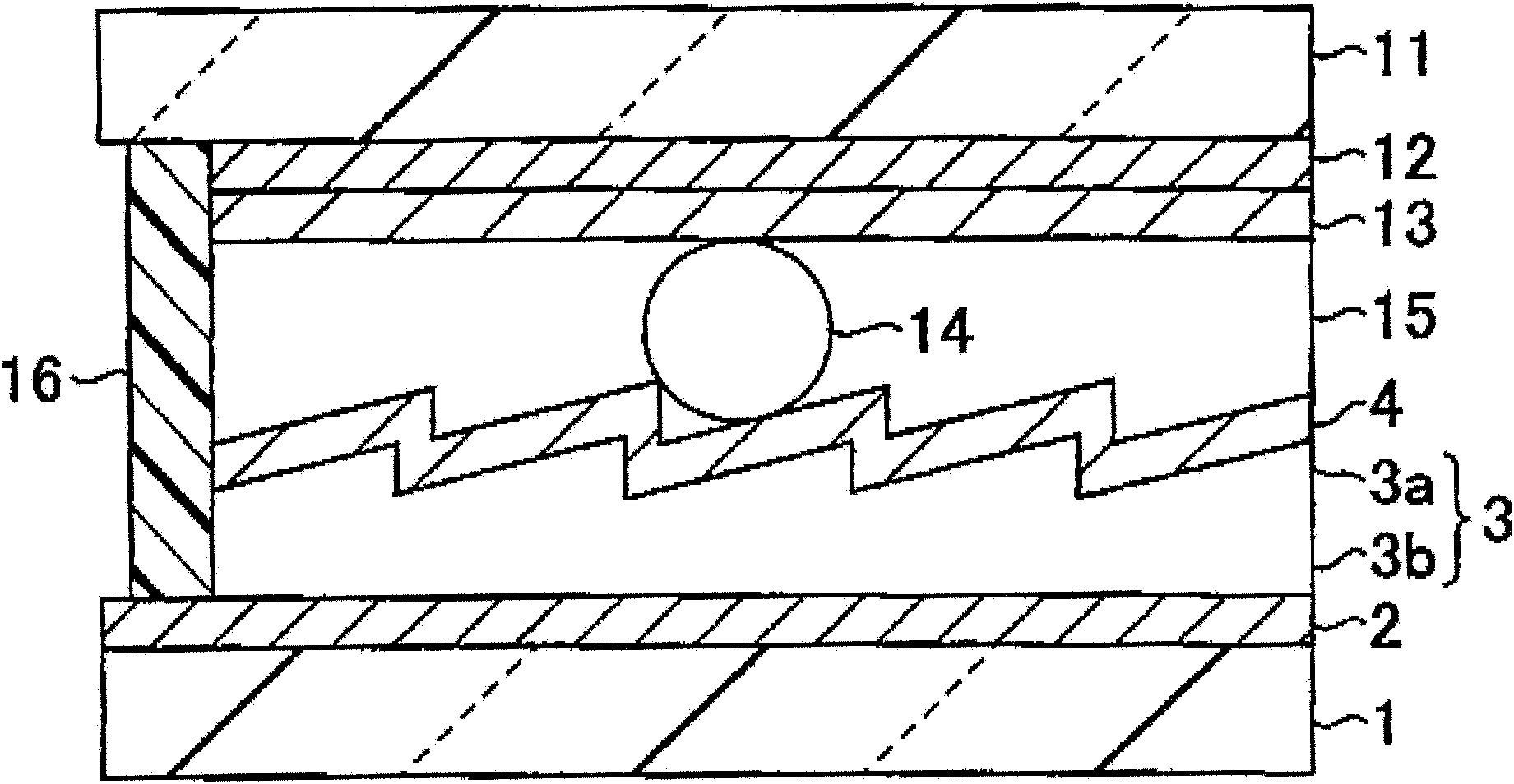
[0023] figure 1 It is a sectional view in the thickness direction schematically showing the light deflection liquid crystal cell of the first embodiment. A pair of glass substrates formed with transparent electrodes (glass substrate 1 formed with transparent electrodes 2 and glass substrate 11 formed with transparent electrodes 12 ) were prepared. The glass substrates 1 and 11 are alkali-free glass and each have a thickness of 0.7 mmt. The transparent electrodes 2 and 12 are formed of indium tin oxide (ITO) and each have a thickness of 150 nm.

[0024] It is preferable that the patterns of the transparent electrodes 2 and 12 are formed in a desired planar shape. The ITO film can be patterned by, for example, wet etching using ferric chloride or a method of removing excess ITO film with a laser.

[0...


PUM


Abstract

The invention provides an optical deflecting device, which is provided with: a liquid crystal layer; a first transparent substrate and a second transparent substrate mutually oppositely disposed and clamping the liquid crystal layer; a first transparent electrode and a second transparent electrode respectively formed at a liquid crystal layer side of the first transparent substrate and the second transparent substrate and applying voltage to the liquid crystal layer; and a prism layer formed at a liquid crystal layer side of either the first transparent substrate or the second transparent substrate, the liquid crystal layer comprises liquid crystal molecules with anisotrophy of dielectric constant be positive, a refractive index of the liquid crystal layer observed from normal directions of the first and second transparent substrates is an average value (2 no+ne) / 3 of an ordinary ray refractive index no and an extraordinary ray refractive index ne in a state that voltage is not applied, the refractive index of the liquid crystal layer is close to the ordinary ray refractive index no via applying of voltage.

Description

technical field [0001] The present invention relates to a light deflection device that performs light deflection for changing the traveling direction of light. Background technique [0002] As a light distribution switching technology for vehicle headlights and the like, a technology using a liquid crystal optical element has been proposed. [0003] Japanese Patent Application Laid-Open No. 2006-147377 discloses a technique of deflecting light using a liquid crystal cell in which a prism is formed on the inner surface of one of a pair of substrates. By switching between a state where a voltage is not applied and a state where a voltage is applied, the refractive index of the liquid crystal layer is changed, thereby changing the traveling direction of light. However, in the technique disclosed in Japanese Patent Laid-Open No. 2006-147377, only one of two polarization components whose polarization directions are perpendicular to each other in incident light entering the liqui...

Claims


Application Information

Patent Timeline
IPC IPC(8): G02F1/29
Inventor 都甲康夫
Owner STANLEY ELECTRIC CO LTD
Why Eureka
Try Eureka