
Built-in aspirator for laparoscope operation

A built-in, laparoscopic technology, applied in the field of medical devices, can solve the problems of increasing the operator's workload and operating time, limited range and angle, and increasing surgical risks, so as to shorten the operating time, reduce the trouble of replacing instruments, and reduce the cost of surgery. risk effect

Inactive Publication Date: 2011-07-20
THE FIRST AFFILIATED HOSPITAL OF THIRD MILITARY MEDICAL UNIVERSITY OF PLA
View PDF4 Cites 5 Cited by
  • Summary
  • Abstract
  • Description
  • Claims
  • Application Information

AI Technical Summary

Problems solved by technology

Laparoscopic surgery requires a small hole in the abdominal wall to serve as a channel for instruments such as forceps, electric hooks, and mirrors to enter and exit the abdominal cavity. Since the position of the instrument needs to be changed according to the operator's operation requirements, there is no small hole dedicated to the entry and exit of a certain instrument. In the abdominal cavity, it is very common for one hole to be used for multiple purposes. At the same time, because the aspirator is a hard tube, the range angle that can be reached is limited. In order to attract liquid from different parts, the position of the aspirator needs to be changed frequently; The aspirator enters and exits the abdominal cavity through different small holes in the abdominal wall multiple times. Such an operation is time-consuming and laborious, and the fluid is not sucked in time, which increases the workload of the surgeon and the operation time, and indirectly increases the risk of the operation.
[0004] In addition, due to the limitation of the puncture card, the diameter of the aspirator is less than 5 mm. During the aspiration, the lumen is often blocked due to the inhalation of soft tissues such as blood clots, intestinal fat, omentum, etc., and the aspiration is forced to be terminated, and even the aspirator needs to be moved. or help with pliers to unblock

Method used


Image

  • Built-in aspirator for laparoscope operation
  • Built-in aspirator for laparoscope operation
  • Built-in aspirator for laparoscope operation

Examples


Embodiment Construction

[0027] Hereinafter, preferred embodiments of the present invention will be described in detail with reference to the accompanying drawings.

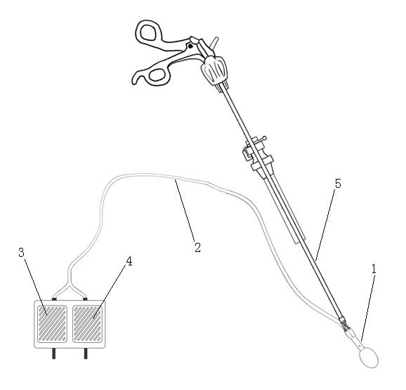
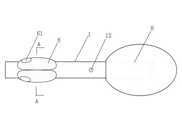
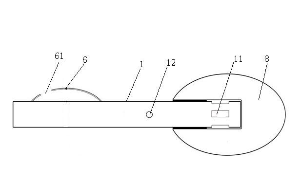
[0028] figure 1 It is a structural schematic diagram of the present invention, figure 2 Schematic diagram of the structure of the suction head, image 3 for figure 2 The schematic diagram of the longitudinal section, Figure 4 for figure 2 A schematic diagram of the A-A section; as shown in the figure, the built-in suction device for laparoscopic surgery of the present invention includes a suction head 1, a hose 2, a suction switch 3 and a flushing switch 4, and one end of the hose 2 communicates with the suction head 1, The other end is divided into two pipes, one of which is connected to the suction switch 3, and the other pipe is connected to the flushing switch 4. The suction head 1 is respectively provided with a suction hole I11 communicated with the hose 2 and a suction hole for gripping by the pliers 5. gripping parts.

...


PUM


Abstract

The invention discloses a built-in aspirator for laparoscope operation, which comprises an aspiration head, a hose, an aspiration switch and a washing switch, wherein one end of the hose is communicated with the aspiration head, the other end of the hose is divided into two pipelines, one of the pipelines is connected with the aspiration switch, and the other pipeline is connected with the washing switch; and an aspiration hole I communicated with the hose and a grasping component for allowing forceps to grasp are respectively formed on the aspiration head. In the operation process, the hose of the aspirator enters enterocoelia from a small hole on an abdominal wall and shares the same small hole with a trocar, so the aspirator is not needed to be removed to leave space for other instruments in the operation process, and the position where the aspirator enters the abdominal wall is not changed any more in the operation process; and the aspirator is in the enterocoelia all the time, sothe aspiration head can be grasped by using the forceps at any time to absorb exudation and seepage, operators absorb the exudation and the seepage instantly and conveniently, and the visual field iskept distinct all the time in the operation process. Simultaneously the trouble of replacing the instruments is reduced, the labor strength of the operators is relieved, the operation time is shortened, and the operation risks are reduced.

Description

technical field [0001] The invention belongs to the technical field of medical instruments, in particular to a laparoscopic operation aspirator. Background technique [0002] In the 21st century, minimally invasive surgery represented by laparoscopy has become an important direction of medical development, and most abdominal visceral operations can be completed under laparoscopy. Due to the cutting and separation of tissues during the operation, fat liquefaction and damage to small blood vessels are caused. It is inevitable to use a suction device to absorb the bleeding and exudate produced by the operation. Peritoneal irrigation is often required towards the end of the procedure, which also requires suction of the irrigation fluid. [0003] At present, the suction device used in laparoscopic surgery is a long tube type, the suction and flushing switch is outside the body, and the suction device enters and exits the abdominal cavity through the puncture hole in the abdomina...

Claims


Application Information

Patent Timeline
IPC IPC(8): A61M27/00A61M3/02A61B17/94
Inventor 钱锋何少波倪嘉李平昂余佩武
Owner THE FIRST AFFILIATED HOSPITAL OF THIRD MILITARY MEDICAL UNIVERSITY OF PLA
Learn More