
Device and method for detecting friction force of continuous casting crystallizer on line

A technology of continuous casting mold and detection device, which is applied to the configuration of indicating equipment/measuring equipment, casting equipment, manufacturing tools, etc., can solve the problems of difficult determination of vibration system parameters, cumbersome work of acceleration sensor, poor practicability and reliability, etc. , to achieve the effect of small workload, strong practicability and small impact

Inactive Publication Date: 2011-07-20
BAOSHAN IRON & STEEL CO LTD +1
View PDF3 Cites 13 Cited by
  • Summary
  • Abstract
  • Description
  • Claims
  • Application Information

AI Technical Summary

Problems solved by technology

The disadvantages of this method are: the work of installing the acceleration sensor in the vibration system is cumbersome, difficult to maintain, seriously disturbed by the environment, and when there is a slight swing in the horizontal horizontal plane of the vibration system, it will have a great impact on the acceleration signal, making The friction force calculated from this has a large error, and the practicability and reliability are poor.
The disadvantage of this method is that it is difficult to determine the parameters of the vibration system in the state of empty vibration of the mold, and it is easy to bring errors to the calculation of friction force

Method used


Image

  • Device and method for detecting friction force of continuous casting crystallizer on line
  • Device and method for detecting friction force of continuous casting crystallizer on line
  • Device and method for detecting friction force of continuous casting crystallizer on line

Examples


Embodiment 1

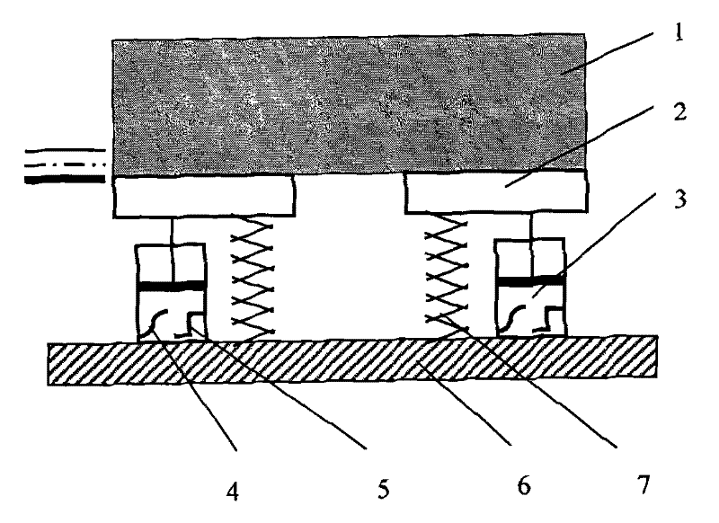
[0058] figure 1 It is a structural schematic diagram of the vibration system. As shown in the figure, the crystallizer 1 is installed on the vibration table 2, and two symmetrical hydraulic cylinders 3 are arranged on both sides below the vibration table. The two hydraulic cylinders are rigidly connected directly with the vibration table. A pressure sensor 4 and a displacement sensor 5 are installed on the cylinder to detect the working pressure and displacement of the hydraulic cylinder. The lower ends of the two hydraulic cylinders are connected with the vibrating table base 6, and a buffer spring 7 is installed between the vibrating table and the vibrating table base. The thick solid line on the left side of the figure represents the lower limit of vibration, the dotted line represents the vibration balance position, and the thin solid line represents the upper limit of vibration. The vibration system vibrates up and down around the preset vibration balance position, which c...

Embodiment 2

[0119] The casting machine used in this example is the same slab test casting machine as in Example 1, the difference is that the inclination of the crystallizer vibration curve is 20°, that is, in the non-sinusoidal vibration mode, the amplitude is 5.0mm, and the air vibration process The vibration frequency is gradually increased from 50cpm to 150cpm, and the casting speed is controlled at 0.8~2.2m / min. The implementation steps and test results are as follows:

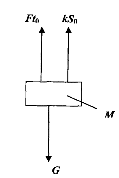
[0120] The first step is to detect the average value Ft of the output force of the hydraulic cylinder when it is still at the vibration balance position 0

[0121] Detect the output force of the hydraulic cylinder within 8 minutes, and calculate the average value of the output force Ft 0 =18.80kN;

[0122] The second step is the determination of the comprehensive stiffness K and equivalent damping B in the air vibration state

[0123] The approximate linear relationship between the comprehensive stiffness K and t...

Embodiment 3

[0130] The casting machine used in this example is a thin slab test casting machine, which produces a thin slab with an end face of 1000mm×80mm, and the total mass of the crystallizer and the vibrating table is 25.8t. The crystallizer vibration mode is non-sinusoidal vibration with a deflection of 40°, the amplitude is 2.2mm, the vibration frequency gradually increases from 90cpm to 195cpm during the empty vibration process, and the casting speed is controlled at 1.0~3.0m / min. The implementation steps and test results are as follows :

[0131] The first step is to detect the average value Ft of the output force of the hydraulic cylinder when it is still at the vibration balance position 0

[0132] Detect the output force of the hydraulic cylinder within 10 minutes, and calculate the average value of the output force Ft 0 =14.22kN;

[0133] The second step is the determination of the comprehensive stiffness K and equivalent damping B in the air vibration state

[0134] The ...


PUM


Abstract

The invention provides a device and method for detecting the friction force of a continuous casting crystallizer on line. The vibrating system of the detecting device comprises hydraulic cylinders (3) each of which is provided with a pressure sensor (4) and a displacement sensor (5), wherein the two hydraulic cylinders are arranged on the two sides below a vibrating table in a bilaterally symmetrical mode; and signals detected by the two sensors are sequentially processed by a programmable controller (8), an analogue / digital (A / D) data acquisition card (9), an industrial personal computer (IPC) (10) and a communication card (11), and are transmitted to a server (12) for data storage. The detecting method comprises the following steps of: measuring the comprehensive rigidity and the equivalent damping of the vibrating system through particle swarm optimization (PSO), performing force analysis on the vibrating system, establishing force equations when the vibrating system keeps still at a vibrating balance position and in a null vibrating state and a throwing state, and calculating the difference between throwing output force and null vibrating output force so as to acquire the friction force of the crystallizer. By using the device and the method, the friction force of the continuous casting crystallizer can be accurately and reliably detected in real time on line.

Description

technical field [0001] The invention belongs to the technical field of metallurgical continuous casting detection. Specifically, the invention relates to a friction detection device and its detection method. The friction detection device and its detection method are an online detection device and its Detection method. Background technique [0002] In the field of metallurgical continuous casting technology, good lubrication between the mold and the slab is very important for the pursuit of high-quality and efficient continuous casting production. Mold friction is an important parameter reflecting the lubrication condition between mold and slab. Specifically, in the design of continuous casting units, mold friction parameters can guide the force analysis of the vibration system, so as to determine reasonable parameters such as vibration dynamics and buffer strength, and provide an important basis for the analysis and calculation of the casting resistance of the unit , so as...

Claims


Application Information

Patent Timeline
IPC IPC(8): B22D2/00B22D11/04B22D11/16
Inventor 张立姚曼叶世鸿王旭东藏欣阳马勇
Owner BAOSHAN IRON & STEEL CO LTD
Learn More