Ignition gun capable of detecting ignition flame

A technology for ignition guns and flames, which is applied in the field of ignition guns, and can solve problems such as no flame monitoring, threats to the personal safety of operators, and impact on accuracy, so as to avoid hidden dangers of safety accidents, simple detection structure, and prolong service life.

Active Publication Date: 2012-05-23
CHONGQING AOKEQI TECH
View PDF1 Cites 0 Cited by
  • Summary
  • Abstract
  • Description
  • Claims
  • Application Information

AI Technical Summary

Problems solved by technology

The ignition guns of the prior art, such as the technical structure disclosed in the utility model patent document named "Electronic Ignition Gun for High-Efficiency and Long-Life Regenerative Burner" and the patent No. ZL03206841.7, mostly only have a single ignition function, no flame Monitoring function; there is a potential safety hazard that the combustible mixed gas in the burner of the combustion device or in the furnace cannot be ignited in time as required. In severe cases, safety accidents such as explosions may occur, causing equipment damage and even threatening the personal safety of operators.
In the prior art, there are also some ignition guns that use a detection device to detect whether the gas in the ignition gun is ignited, but due to reasons such as small capacity and narrow installation space, most of them add a set of complicated detection devices outside the ignition gun. The detection effect is not ideal, and the detection probe is usually located in the high temperature area of ​​the flame, and it will be burned out after a long time, resulting in a short life span and affecting the accuracy of detection

Method used


Image

  • Ignition gun capable of detecting ignition flame
  • Ignition gun capable of detecting ignition flame
  • Ignition gun capable of detecting ignition flame

Examples


Embodiment Construction

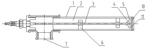
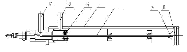
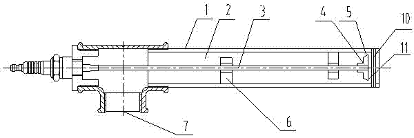
[0014] The ignition gun that can detect ignition flame of the present invention comprises ignition power supply and gun barrel 1, and the surface layer of gun barrel 1 or whole is the metal gun barrel that conductive metal material is made of, and the inside of gun barrel 1 is cavity 2, and The ignition needle 3 connected to the ignition power supply is arranged in the cavity 2, one end of the ignition needle 3 is connected to the ignition power supply, and the other end is provided with an ignition electrode 4, and a certain width dimension is formed between the side of the ignition electrode 4 and the inner wall of the gun barrel 1. The ignition chamber 5, the width of the ignition chamber 5 is about 3mm, after the ignition power supply (high voltage) is communicated with the ignition needle 3 and the ignition electrode 4 through the corresponding control switch, the side of the ignition electrode 4 and the inner wall of the gun barrel 1 are in the ignition chamber. Discharge...


PUM


Abstract

The invention discloses an ignition gun capable of detecting ignition flame, which comprises an ignition power supply and a gun barrel, wherein the gun barrel is a metal gun barrel, the interior of the gun barrel is a cavity, an ignition needle connected with the ignition power supply is arranged in the cavity, the other end of the ignition needle is provided with an ignition electrode, an ignition cavity is formed between the lateral surface of the ignition electrode and the inner wall of the gun barrel, the ignition needle is arranged in the cavity through one or more limit insulated supporting blocks, and the gun barrel is provided with a combustible gas inlet; and a detection metal strip is arranged at the front end of the gun barrel, a clearance is formed between the detection metal strip arranged in the radial direction and the front of the ignition electrode so as to form a detection cavity, and two ends of the detection metal strip are communicated with the metal layers of thegun barrel respectively. The ignition gun can timely ignite the combustible gas so as to improve the safety of the combustible gas, prevent the combustible gas from being gathered due to untimely ignition, effectively prevent a combustion device from blasting and avoid potential safety accidents; and the detection metal strip is positioned in a low temperature zone, so the detection metal strip is prevented from being burnt, and the service life of the detection metal strip is effectively prolonged.

Description

technical field [0001] The invention relates to an ignition gun for igniting gas in a gas furnace, in particular to an ignition gun capable of detecting ignition flames by means of ion detection. Background technique [0002] The ignition gun is used as an ignition device for igniting the combustible mixed gas in the combustion device. It is used in medium-sized and large-scale combustion devices such as coal gas, liquefied petroleum gas, and natural gas. It is an important auxiliary equipment for the combustion device. The sparks generated by the high-voltage discharge between the bodies ignite the combustible gas in it, and then ignite the gas in the main burner through the flame of the ignition gun; The combustible mixed gas inside is ignited to prevent the accumulation of combustible mixed gas due to failure to ignite in time. If it is not ignited in time, there will be dangers such as explosion. The ignition guns of the prior art, such as the technical structure disclo...

Claims


Application Information

Patent Timeline
Patent Type & Authority Patents(China)
IPC IPC(8): F23Q3/00
Inventor 顾向涛
Owner CHONGQING AOKEQI TECH
Why Eureka
Try Eureka