Multi-lane motor vehicle tail gas detection system

A technology for exhaust gas detection and motor vehicles, which is applied in the traffic control system of road vehicles, traffic control systems, TV system components, etc., can solve the problem of inability to detect the concentration of exhaust pollutants from multiple motor vehicles and the inability to accurately detect the concentration of exhaust pollutants Detection and other problems to achieve accurate detection results

Active Publication Date: 2011-07-20
UNIV OF SCI & TECH OF CHINA +1
View PDF4 Cites 39 Cited by
  • Summary
  • Abstract
  • Description
  • Claims
  • Application Information

AI Technical Summary

Problems solved by technology

When there are motor vehicles passing by in multiple lanes, the infrared light received by the infrared receiver and the ultraviolet light received by the ultraviolet receiver are absorbed by the exhaust of multiple motor vehicles, so only the sum of the exhaust pollutant concentrations of multiple motor vehicles can be detected , to achieve a preliminary analysis of the concentration of exhaust pollutants from multiple motor vehicles, but it is impossible to accurately detect the concentration of exhaust pollutants of each motor vehicle
It can be seen that the above-mentioned multi-lane motor vehicle exhaust telemetry device has the following disadvantages: the exhaust pollutant concentration of the motor vehicle can be accurately detected when there is only one motor vehicle passing on the multi-lane. Detect the concentration of exhaust pollutants of multiple motor vehicles separately

Method used


Image

  • Multi-lane motor vehicle tail gas detection system
  • Multi-lane motor vehicle tail gas detection system
  • Multi-lane motor vehicle tail gas detection system

Examples


Embodiment 1

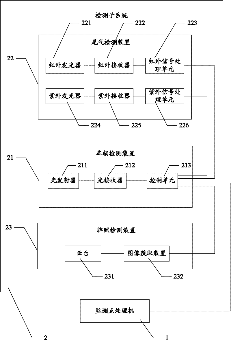
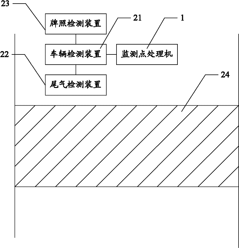
[0028] See figure 1 with figure 2 , figure 1 It is a schematic structural diagram of a multi-lane motor vehicle exhaust detection system disclosed in the first embodiment of the present invention, figure 2 for figure 1 The spatial structure diagram of the multi-lane motor vehicle exhaust detection system is shown.

[0029] The system includes: a monitoring point processor 1 and a detection subsystem 2 arranged in each lane.

[0030] Among them, the detection subsystem 2 includes: a vehicle detection device 21, an exhaust gas detection device 22, a license plate detection device 23, and a reflection belt 24 laid on the road surface.

[0031] The vehicle detection device 21 includes a light transmitter 211, a light receiver 212, and a control unit 213. The light emitter 211 and the light receiver 212 are arranged above the reflective belt 24 in a group. The light emitted by the light emitter 211 is transmitted to the reflective belt 24 and is reflected by the reflective belt 24. The ...

Embodiment 2

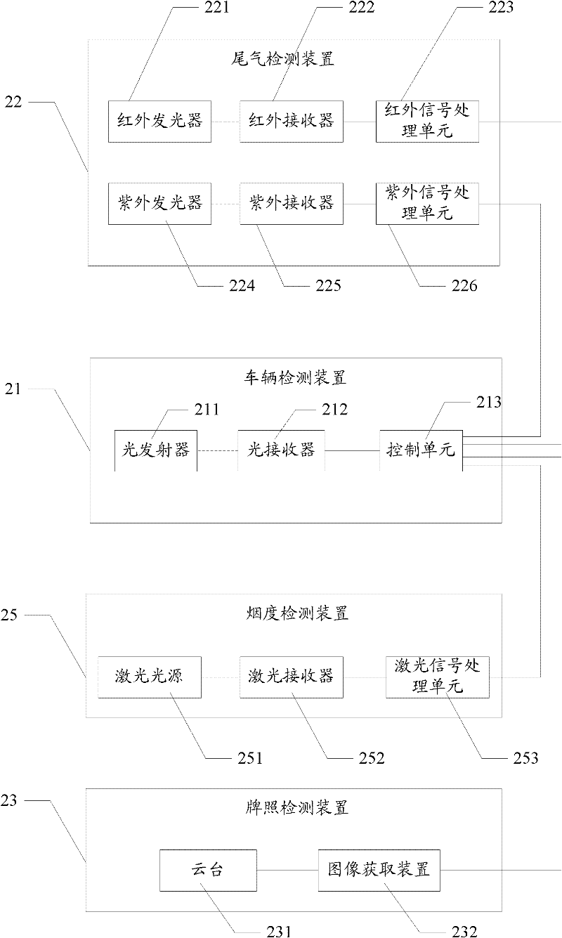
[0043] See image 3 , image 3 It is a schematic structural diagram of the detection subsystem in the multi-lane motor vehicle exhaust detection system disclosed in the second embodiment of the present invention.

[0044] The detection subsystem 2 includes: a vehicle detection device 21, an exhaust gas detection device 22, a license plate detection device 23, a reflection belt (not shown in the figure) laid on the road surface, and a smoke detection device 25. The structures of the vehicle detection device 21, the exhaust gas detection device 22, the license plate detection device 23, and the reflection belt are the same as those of the corresponding devices in the first embodiment, and will not be repeated here.

[0045] The smoke detection device 25 includes a laser light source 251, a laser receiver 252 and a laser signal processing unit 253. The laser light source 251 and the laser receiver 252 are arranged above the reflective belt in a group. The laser light emitted by the la...

Embodiment 3

[0054] See Figure 4 with Figure 5 , Figure 4 It is a schematic structural diagram of the detection subsystem in the multi-lane motor vehicle exhaust detection system disclosed in the third embodiment of the present invention, Figure 5 for Figure 4 The schematic diagram of the space structure of the vehicle detection device in the detection subsystem shown. Figure 5 The direction indicated by the middle arrow is the direction of travel of the vehicle.

[0055] The detection subsystem includes: a vehicle detection device 21, an exhaust gas detection device 22, a license plate detection device 23, a reflection belt 24 laid on the road surface, and a smoke detection device 25. The structures of the exhaust gas detection device 22, the license plate detection device 23, the reflection belt 24, and the smoke detection device 25 are the same as those of the corresponding devices in the second embodiment, and will not be repeated here.

[0056] The vehicle detection device 21 inclu...


PUM


Abstract

The invention discloses a multi-lane motor vehicle tail gas detection system, which comprises a monitoring point processor and detection sub-systems in lanes. Each detection sub-system comprises a vehicle detection device, a tail gas detection device, a license plate detection device and a reflection zone. Each tail gas detection device comprises an infrared light emitter, an infrared light receiver, an infrared signal processing unit, an ultraviolet light emitter, an ultraviolet light receiver and an ultraviolet signal processing unit, wherein the infrared light emitter and the infrared light receiver are arranged in pair above the reflection zone and the ultraviolet light emitter and the ultraviolet light receiver are arranged in group above the reflection zone. Each tail gas detection device comprises a cradle head and an image acquisition device. Each vehicle detection device comprises a light emitter, a light receiver and a control unit, wherein the light emitter and the light receiver are arranged above the reflection zone. In the system disclosed by the invention, as the infrared rays and the ultraviolet rays in each lane are transmitted in directions which are perpendicular to each other approximately, the pollutant concentrations in tail gases of motor vehicles in the lanes can be detected at the same time without mutual interference, namely the pollutant concentrations in tail gases of motor vehicles in the lanes can be detected accurately at the same time.

Description

Technical field [0001] The invention relates to the technical field of environmental detection, in particular to a multi-lane motor vehicle exhaust detection system. Background technique [0002] With the rapid development of social economy and the improvement of people’s living standards, the number of motor vehicles is increasing year by year, and the negative impact of motor vehicle exhaust on the urban atmospheric environment is also increasing. The main manifestations are human respiratory diseases and excessive surface ozone. High, increase the urban heat island effect and produce photochemical smog. Therefore, the importance of detecting the concentration of motor vehicle exhaust pollutants is becoming increasingly apparent. [0003] At present, the most commonly used methods for detecting motor vehicle exhaust at home and abroad are: no-load test method (including idle speed method, idle speed / high idle speed method, dual idle speed method and free acceleration test method...

Claims


Application Information

Patent Timeline
Patent Type & Authority Applications(China)
IPC IPC(8): G01N21/33G01N21/35G01N21/17H04N5/225G08G1/017G01N21/3504
Inventor 康宇洪顺坤胡勇胡峰
Owner UNIV OF SCI & TECH OF CHINA
Why Eureka
Try Eureka