Cutting drilling machine

A drilling rig and drilling stand technology, which is used in rotary drilling rigs, earth-moving drilling, drilling equipment and other directions, can solve the problems of stuck drill bits, poor performance of the whole machine, inconvenient operation, etc., so as to improve the drilling work. The effect of high quality, fast hole forming speed and convenient operation

Inactive Publication Date: 2011-07-27
HANGZHOU HANGZHONG CONSTR MACHINERY
View PDF11 Cites 5 Cited by
  • Summary
  • Abstract
  • Description
  • Claims
  • Application Information

AI Technical Summary

Problems solved by technology

However, in the prior art including this technology, there is a common phenomenon that the center of gravity is behind, and when drilling, it is easy to lift, so that the drilling is crooked, and the drill bit is stuck and cannot be pulled out; and, when encountering a hard surface, the protection Insufficient, the strength of the boom, drill frame and related parts is low, easy to crack and damage; the above factors lead to poor working performance of the whole machine, insufficient downforce, slow hole forming speed, and inconvenient operation

Method used


Image

  • Cutting drilling machine
  • Cutting drilling machine
  • Cutting drilling machine

Examples


Embodiment 1

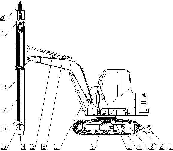
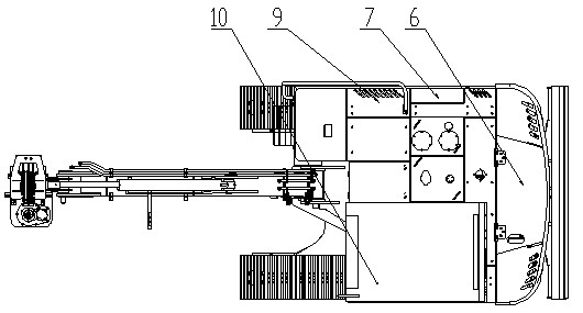
[0017] Example 1: Such as figure 1 , 2 As shown, the cutting drilling rig of this embodiment consists of a bulldozing blade 1, a bulldozing cylinder 2, a chassis assembly 3, a slewing mechanism 4, a platform assembly 5, a power system 6, a hydraulic system 7, a cab 8, an air compressor system 9. Operating system 10, boom cylinder 11, boom 12, drill frame cylinder 13, drill bit 14, guide limit sleeve 15, travel switch 16, drill frame 17, drill rod 18, power head system 19 and drill rod propulsion system 20 composition.

[0018] Chassis assembly 3 is the walking and chassis part of the present invention. It is set at the bottom end and directly touches the ground. It uses 8.5T four wheels and 450mm widened track shoes to reduce the ground pressure and ensure the stability of the whole machine. Larger drill pipe down pressure improves the efficiency of drilling rigs. A slewing mechanism 4 is provided on the top, and the slewing mechanism 4 can freely rotate 360 ​​degrees on the cha...


PUM


Abstract

The invention relates to a cutting drilling machine, belonging to the field of heavy-duty machinery. The cutting drilling machine comprises a chassis assembly, a slewing mechanism, a platform assembly, a power system, a hydraulic system, an operating system, a movable arm cylinder, a movable arm, a drilling frame cylinder, a drill, a drilling frame, a drill stem, a power head system and a drill stem propulsion system, wherein the chassis assembly is arranged at the lowest end; the platform assembly is connected with the chassis assembly via the slewing mechanism and is arranged above the chassis assembly; the power system, the hydraulic system and the operating system are connected with each other and are arranged on the platform assembly; the power system is connected with the chassis assembly; one end of the movable arm cylinder is hinged on the platform assembly and the other end of the movable arm cylinder is hinged with the movable arm; one end of the drilling frame cylinder is hinged on the movable arm and the other end of the drilling frame cylinder is hinged with the drilling frame; the movable arm is connected with the drilling frame; the drill stem propulsion system is arranged above the drilling frame; the power head system, the drill stem and the drill are arranged in the drilling frame from top to bottom ins sequence; and the hydraulic system is connected with the drilling frame cylinder, the movable arm cylinder and the drill stem propulsion system respectively.

Description

Technical field [0001] The invention relates to a cutting drill, which belongs to the field of heavy machinery. Background technique [0002] Existing cutting drilling rig products, such as a full hydraulic multi-azimuth down-the-hole drilling rig disclosed in the patent number 200520052467.7, which is specifically suitable for blast hole drilling in metallurgy, coal, building materials, railway, hydropower construction, national defense construction and other projects Fully hydraulic multi-azimuth down-the-hole drilling rig used in geotechnical anchoring projects for operations, hydropower, transportation, energy, and urban foundation pit support. The air compressor and the hydraulic pump are respectively installed on the flywheel housing and side force take-off of the engine; the drilling angle adjustment mechanism is composed of a tripod, a pitch cylinder, and a swing angle cylinder. One end of the tripod is hinged with the boom through a hinge shaft. The oil cylinder drives ...

Claims


Application Information

Patent Timeline
Patent Type & Authority Applications(China)
IPC IPC(8): E21B7/02E21B3/02E21B15/00
Inventor 陈顺牛任贵东王李波顾孙强苏家斌张焘李静寅吴大可吴斌袁江琴
Owner HANGZHOU HANGZHONG CONSTR MACHINERY
Why Eureka
Try Eureka