Synchronous light pen electronic whiteboard system

一种电子白板、同步光的技术,应用在电数字数据处理、仪器、数据处理的输入/输出过程等方向,能够解决效果有限、光干扰、电池耗尽等问题,达到改善使用效果、提高信噪比的效果

Inactive Publication Date: 2011-07-27
TALLPIC INTELLIGENCE TECH
View PDF4 Cites 24 Cited by
  • Summary
  • Abstract
  • Description
  • Claims
  • Application Information

AI Technical Summary

Problems solved by technology

However, the effect achieved by only using optical filters is limited. Under a certain light pen brightness, if the ambient light is strong, light interference is still prone to occur, and if the luminous power is increased excessively, it will lead to high power consumption and battery run out quickly

Method used


Image

  • Synchronous light pen electronic whiteboard system
  • Synchronous light pen electronic whiteboard system
  • Synchronous light pen electronic whiteboard system

Examples


Embodiment Construction

[0012] The present invention will be further described below in conjunction with the accompanying drawings and embodiments.

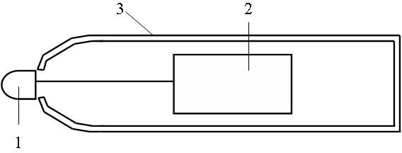
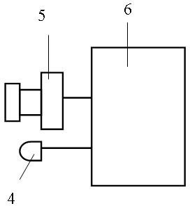
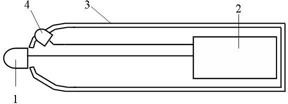
[0013] figure 1 and figure 2 A schematic diagram of the composition of a specific embodiment of the synchronous light pen electronic whiteboard system of the present invention is given together. The light-emitting device 1 at the head of the pen is an infrared emitting tube, located at the head of the pen and connected to the light pen circuit 2, and located in the housing 3. This is the usual setup of the prior art. The light pen circuit 2 is a circuit composed of a common single-chip microcomputer as the core. Under the control of the single-chip microcomputer, when the light pen emits light, the width of its light-emitting pulse is about 5 milliseconds, and the pulse period is about 20 milliseconds. At the same time, each pulse is modulated at on a 38KHz carrier. The synchronous signal receiver 4 is a common 38KHz infrared receiving module for i...


PUM


Abstract

The invention discloses a synchronous light pen electronic whiteboard system. In the system, an image sensor with a global shutter is arranged in a signal receiving device; a light pen is used for emitting light in a pulse mode; a synchronous signal emitter and a synchronous signal receiver are arranged in the system; the pulse light emitting time of the light pen can be coincided with the exposure time of the image sensor through a synchronous signal, so that the aim of improving the signal-to-noise ratio is fulfilled; and the synchronous signal emitter is arranged in the light pen, and the synchronous signal receiver is arranged in the signal receiving device; or the synchronous signal emitter is arranged in the signal receiving device, and the synchronous signal receiver is arranged inthe light pen. By the two schemes, the light emitting pulse time can be coincided with the exposure time, and the aim can be fulfilled. Due to the adoption of the schemes, the power consumption of the light pen can be effectively reduced, and the signal-to-noise ratio of the system can also be effectively improved.

Description

technical field [0001] The invention relates to an electronic whiteboard system, in particular to a synchronous light pen electronic whiteboard system using optical image technology. technical background [0002] The electronic whiteboard system using optical image technology is based on the position tracking of the light pen, which is detailed in the Chinese invention patent No. ZL011080477, invention patent publication No. CN1305143A, and the name "system and method for computer coordinate and control information input". describe. Its working principle is: use the light point generated by the light pen to mark the position of the target point, introduce the camera device to collect images in real time, use the signal processing circuit to analyze the image signal in real time and extract the position information of the light point, and input it to the computer through the interface circuit and corresponding software , using the coordinate correction algorithm for coordina...

Claims


Application Information

Patent Timeline
Patent Type & Authority Applications(China)
IPC IPC(8): G06F3/042
CPCG06F3/0425G06F3/042G06F3/03542G06F3/0386
Inventor 鲍炜
Owner TALLPIC INTELLIGENCE TECH
Why Eureka
Try Eureka