Converter circuit, and motor drive controller equipped with converter circuit, air conditioner, refrigerator, and induction cooking heater

A converter circuit and converter technology, applied in the direction of AC motor control, induction heating, induction heating control, etc., can solve the problems that the circuit cannot be small and light, and achieve the effect of reducing switching loss and reducing inductance value

Active Publication Date: 2011-07-27
MITSUBISHI ELECTRIC CORP
View PDF10 Cites 30 Cited by
  • Summary
  • Abstract
  • Description
  • Claims
  • Application Information

AI Technical Summary

Problems solved by technology

[0005] When using a boost converter, a buck converter, or a buck-boost converter as a power factor improvement circuit, it is necessary to make the current flowing through the rea...

Method used


Image

  • Converter circuit, and motor drive controller equipped with converter circuit, air conditioner, refrigerator, and induction cooking heater
  • Converter circuit, and motor drive controller equipped with converter circuit, air conditioner, refrigerator, and induction cooking heater
  • Converter circuit, and motor drive controller equipped with converter circuit, air conditioner, refrigerator, and induction cooking heater

Examples


Embodiment approach 1

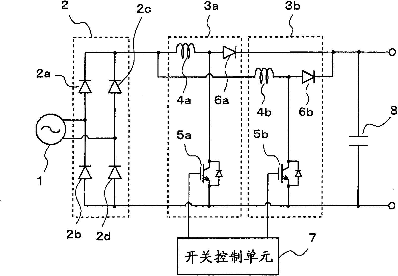
[0030] figure 1 It is a block diagram of the converter circuit concerning Embodiment 1 of this invention.

[0031] exist figure 1 Among them, the rectifier 2 for rectifying the AC voltage of the commercial power supply 1 has a structure in which four rectifier diodes 2a to 2d are connected in bridge form. To the output of the rectifier 2, a boost converter 3a as a first converter unit and a boost converter 3b as a second converter unit are connected in parallel.

[0032] The boost converter 3a is composed of: a boost reactor 4a as a first reactor; and a switching element 5a as a first switching element, for example, an IGBT (Insulated Gate Bipolar Transistor: Insulated Gate Bipolar Transistor) or the like. ; and the backflow prevention element 6a as the first backflow prevention unit is composed of, for example, a fast recovery (fast recovery) diode or the like. In addition, the boost converter 3b is also composed of the following parts in the same manner: a boost reactor 4...

Embodiment approach 2

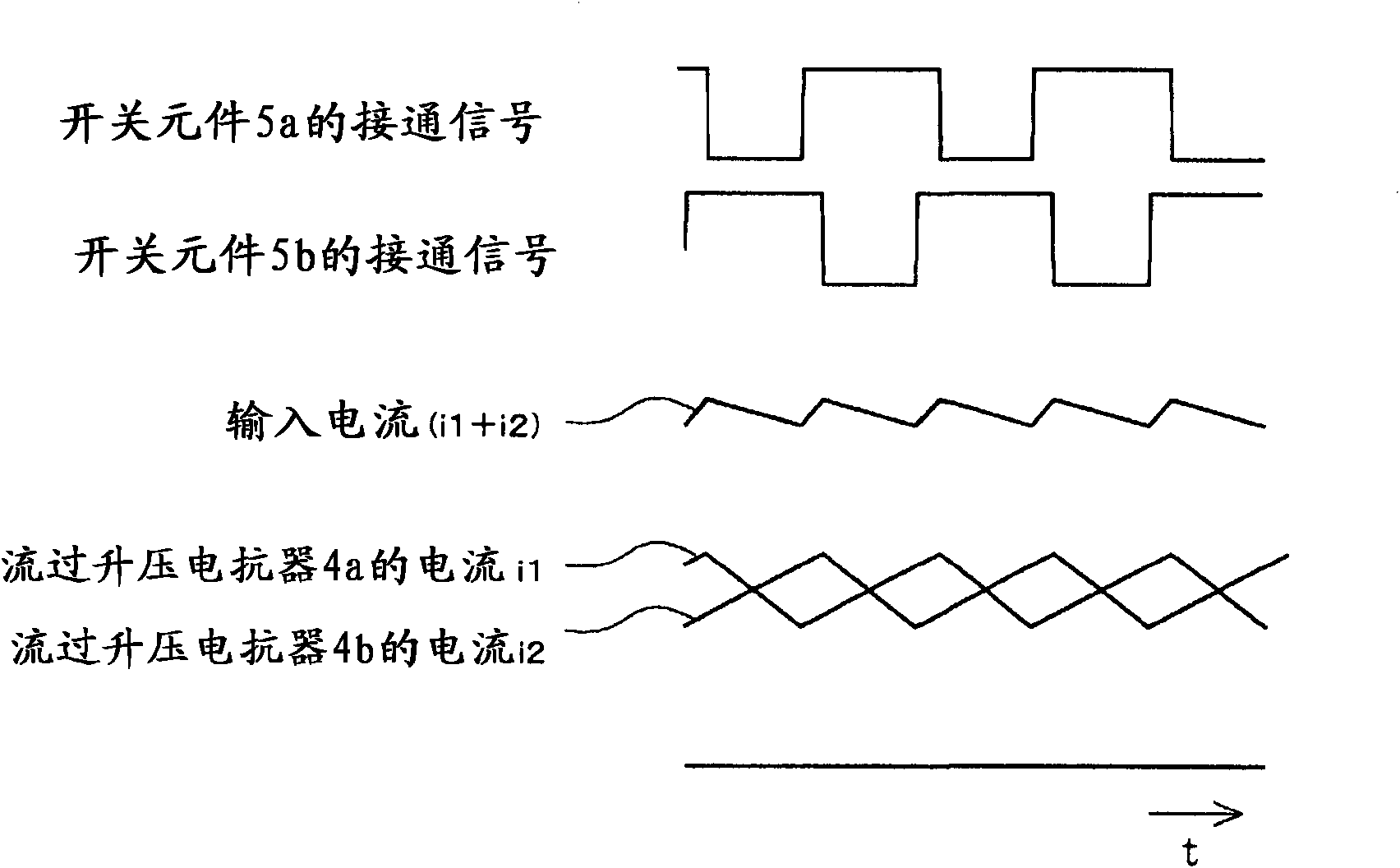
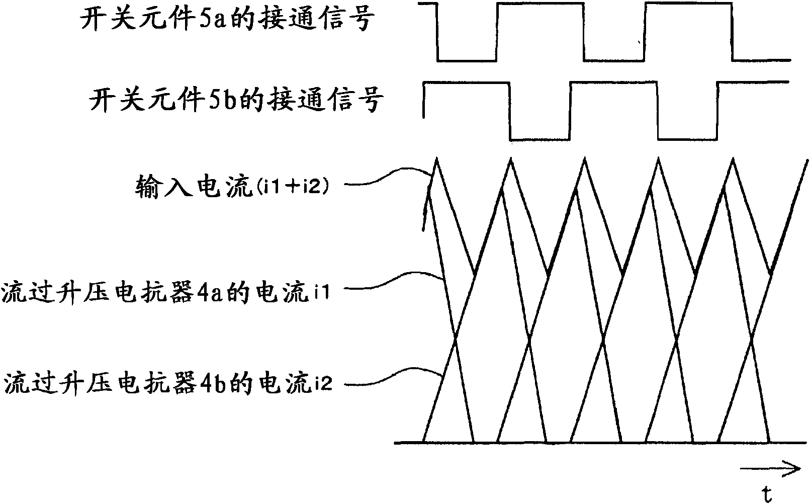
[0068] In the first embodiment described above, the current mode of the current flowing through the boost reactor 4 is set to be the critical mode or the discontinuous mode by operation. In Embodiment 2, by switching the current mode during operation, operations utilizing the characteristics of each current mode can be performed.

[0069] Here, the characteristics of each current mode will be described.

[0070] In the case of controlling in the continuous mode, compared with the critical mode and the discontinuous mode, the current ripple rate is small, and the generation of harmonic components of the input current can be suppressed. On the other hand, since the switching frequency becomes higher than in the critical mode and the discontinuous mode, the switching loss in the switching element 5 and the backflow prevention element 6 becomes large.

[0071] In the case of operating in the critical mode, the current ripple rate is smaller than that in the discontinuous mode, an...

Embodiment approach 3

[0120] In Embodiment 1 or 2 above, a case where two boost converters are used has been described, but in Embodiment 3, three or more boost converters are used.

[0121] Figure 9 It is a configuration diagram of a converter circuit according to Embodiment 3 of the present invention.

[0122] Such as Figure 9 As shown, the converter circuit in the third embodiment includes a boost converter 3c connected in parallel to the boost converters 3a and 3b in addition to the configuration of the above-mentioned first embodiment.

[0123] Similarly, the boost converter 3c is composed of: a boost reactor 4c as a reactor in the present invention; a switching element 4c as a switching element in the present invention, for example, is composed of an IGBT or the like; The backflow prevention element 6c of the backflow prevention element in the present invention is constituted by, for example, a fast recovery diode or the like.

[0124] In addition, other structures are the same as those ...


PUM


Abstract

Provided are a converter circuit which can be made compact and lightweight while reducing switching loss, and a motor drive controller equipped with the converter circuit, an air conditioner, a refrigerator, and an induction cooking heater. The converter circuit comprises a rectifier (2), a step-up converter (3a) having a step-up reactor (4a), a switching element (5a) and a reverse current prevention element (6a), a step-up converter (3b) having a step-up reactor (4b), a switching element (5b) and a reverse current prevention element (6b) and being connected in parallel with the step-up converter (3a), a switching control means (7) for controlling the switching elements (5a, 5b), and a smoothing capacitor (8) provided at the output of the step-up converters (3a, 3b), wherein the switching control means (7) switches the current mode of a current flowing through the step-up reactors (4a, 4b) to any one of a continuous mode, a critical mode or a discontinuous mode based on predetermined conditions.

Description

technical field [0001] The present invention relates to a converter circuit, a motor drive control device, an air conditioner, a refrigerator, and an induction heating cooker provided with the converter circuit. Background technique [0002] Conventionally, as a power factor correction (PFC) circuit, in addition to a boost converter, a buck converter and a buck-boost converter are generally used. [0003] In addition, in order to reduce the size and weight of the converter circuit, for example, it is proposed to include a "rectifier circuit, which uses an AC power supply as an input; a first step-up converter circuit, which is connected to the output of the rectifier circuit, and has at least a first reactance A device, a first switching unit, and a first diode; a second boost converter circuit, connected in parallel to the first boost converter circuit, at least having a second reactor, a second switching unit, and a second diode; and a smoothing capacitor connected to the...

Claims


Application Information

Patent Timeline
IPC IPC(8): H02M3/158H02M1/12H05B6/06
CPCH05B6/06Y02B70/126H02M3/1584H02M2003/1586H02M1/4225H02M3/1586Y02B70/10H02M7/06H02P27/06
Inventor 下麦卓也篠本洋介坂廼边和宪山田伦雄畠山和德
Owner MITSUBISHI ELECTRIC CORP
Why Eureka
Try Eureka