Rectification-type self-overlaying gas liquefying system

A self-cascading and rectifying technology, used in refrigeration and liquefaction, fluid circulation arrangement, lighting and heating equipment, etc. problems, to achieve the effect of reducing unit liquefaction work, ensuring reliable operation, and reducing heat transfer temperature difference

Active Publication Date: 2011-08-03
ZHEJIANG UNIV
View PDF6 Cites 9 Cited by
  • Summary
  • Abstract
  • Description
  • Claims
  • Application Information

AI Technical Summary

Problems solved by technology

However, the above-mentioned system is only suitable for general refrigeration, and the overall structure is complex. In addition, the above-mentioned refrigeration system does not consider the water equivalent ratio between the refrigerant and the liquefied gas, and the heat transfer temperature difference is large during operation, resulting in large heat loss.

Method used


Image

  • Rectification-type self-overlaying gas liquefying system
  • Rectification-type self-overlaying gas liquefying system
  • Rectification-type self-overlaying gas liquefying system

Examples


Embodiment 1

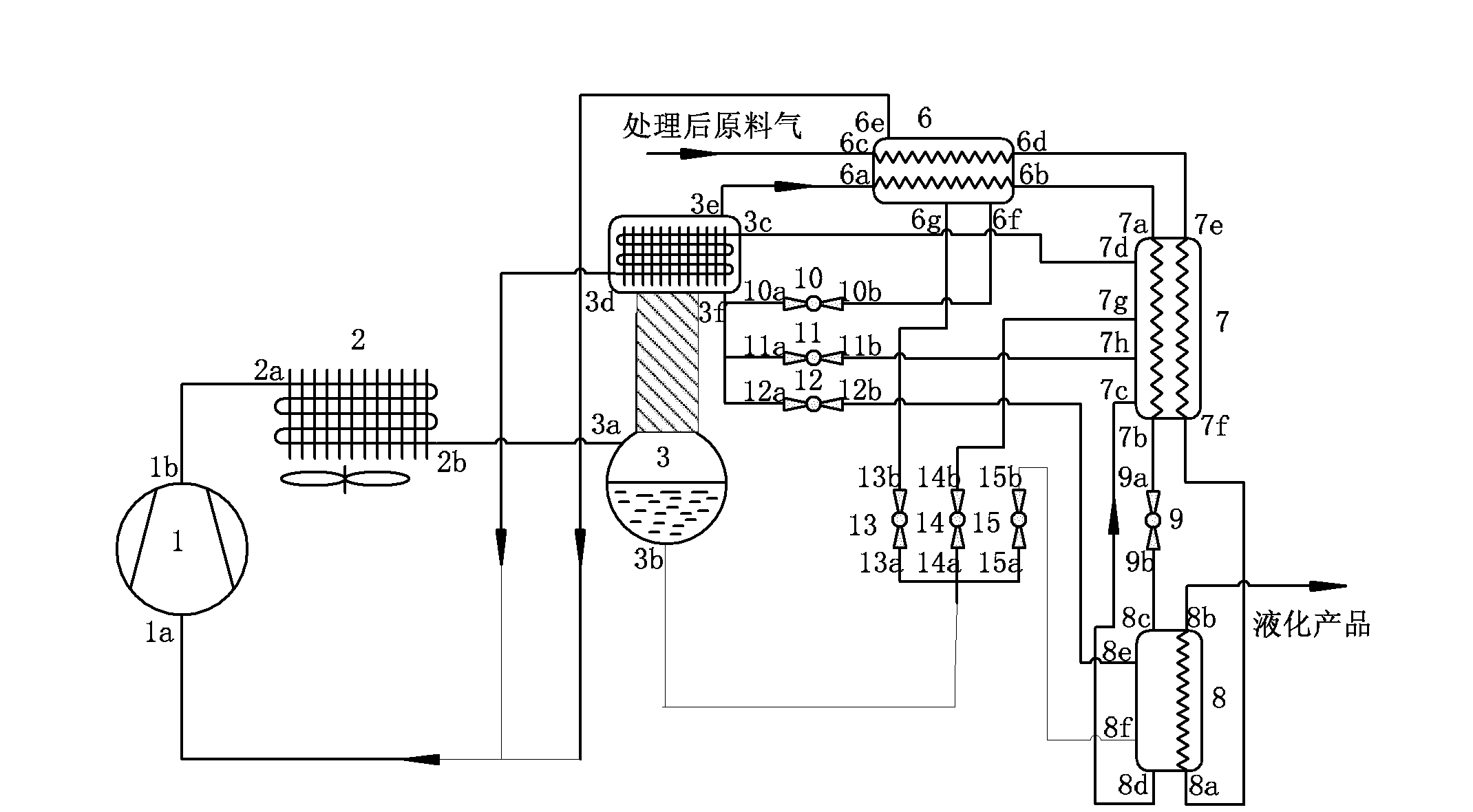
[0023] as attached figure 1 As shown, a rectification type self-cascading gas liquefaction system includes a compressor 1, a condenser 2, a rectification device 3, a first heat exchanger 6, a second heat exchanger 7, a third heat exchanger 8, The first throttle element 9 , the second throttle element 10 , the third throttle element 11 , the fourth throttle element 12 , the fifth throttle element 13 , the sixth throttle element 14 , and the seventh throttle element 15 . The rectification device 3 includes a rectification tower and a tower top heat exchanger communicated with the top of the rectification section of the rectification tower. Both the first heat exchanger 6 and the second heat exchanger 7 are provided with a refrigerant pipeline and a raw material gas liquefaction pipeline, and a plurality of feeding or discharging ports communicating with the inner cavity are arranged on the outer wall. The third heat exchanger 8 is provided with a feed gas liquefaction pipeline,...

Embodiment 2

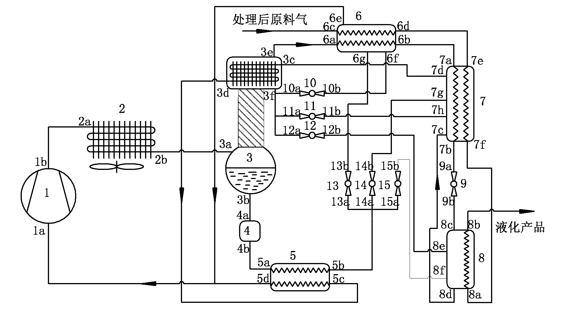
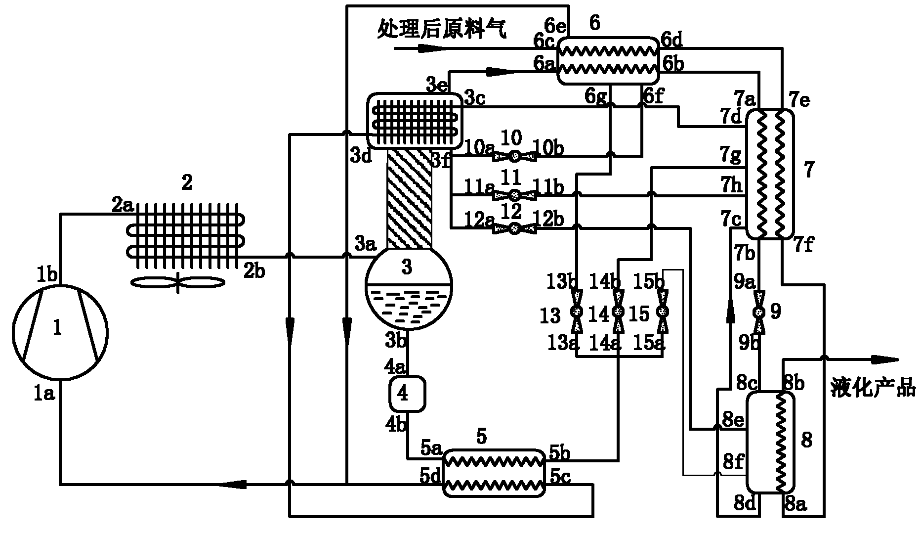
[0040] The only difference from Example 1 is that a dry filter 4 and a tank bottom heat exchanger 5 are provided between the bottom of the rectification column and the fifth throttling element 13 or the sixth throttling element 14 or the seventh throttling element 15 . Wherein, the liquid outlet 3b at the bottom of the rectifying tower of the rectifying device 3 is connected to the feed port 4a of the dry filter 4 earlier, and the discharge port 4b of the dry filter 4 is connected to one of the pipes in the heat exchanger 5 at the bottom of the tank. The inlet end 5a is connected, and the outlet end 5b of the pipeline is connected with the feed port of the fifth throttling element 13 or the sixth throttling element 14 or the seventh throttling element 15 respectively; The inlet end 5c of a pipeline is connected, and the outlet end 5d of this pipeline is communicated with the suction port 1a of the compressor 1; On both sides of the pipe, ensure the reverse flow of materials i...


PUM


Abstract

The invention discloses a rectification-type self-overlaying gas liquefying system, which comprises a compressor, a condenser, a rectifying device and a raw material gas liquefying loop. A discharging port of the compressor is connected with a feeding port of the condenser; a discharging port of the condenser is connected with a feeding port in a kettle of the rectifying device; the rectifying device comprises a rectifying tower and a tower top heat exchanger, wherein the tower top heat exchanger is communicated with the top of a rectifying section of the rectifying tower; a discharging port at the top of the tower top heat exchanger is connected with the raw material gas liquefying loop; and the raw material gas passes through the raw material gas liquefying loop and a final liquefying product is obtained. In the invention, a multi-stage separation process of the traditional mixed working medium liquefying system is replaced by the rectifying device, the high-pressure liquids with different components led out from the bottom and the top of the rectifying device are respectively subject to pressure reduction to enter the raw material gas liquefying loop, the change of the water equivalent weight in the temperature-reduction liquefying process is matched in an optimized way so that the raw material gas is cooled section by section. The rectification-type self-overlaying gas liquefying system has the advantages of simple structure, reliability in operation, high system liquefying efficiency and the like, and is particularly suitable for various mini-type and micro-type gas liquefying systems.

Description

technical field [0001] The invention relates to a gas liquefaction system, in particular to a rectification type self-cascading gas liquefaction system. Background technique [0002] In large-scale natural gas liquefaction projects, the mixed refrigerant self-cascade gas liquefaction system has replaced the classic cascade gas liquefaction system and has been widely used. However, since these traditional mixed refrigerant gas liquefaction systems adopt a 2-5 stage equilibrium separation and segregation process, the treatment of lubricating oil has been greatly improved, but the structure of the cycle has become correspondingly complicated, and the operation process has a great impact on The adaptability of air source and ambient temperature becomes poor and difficult to control. Especially for small and micro gas liquefaction devices, simplicity of equipment is a very important determining factor, and the above-mentioned traditional liquefaction system cannot adapt to the m...

Claims


Application Information

Patent Timeline
Patent Type & Authority Applications(China)
IPC IPC(8): F25B1/00F25B41/06
Inventor 王勤王江浦陈光明张爱民刘锐
Owner ZHEJIANG UNIV
Why Eureka
Try Eureka