
Current source switching circuit for current rudder digital/analog converter

A technology of analog converter and current rudder number, applied in the field of current source switching circuit, can solve the problems of output harmonic distortion and output signal fluctuation, and achieve the effect of reducing harmonic distortion and improving performance

Inactive Publication Date: 2011-08-03
SHANGHAI BEILING
View PDF3 Cites 5 Cited by
  • Summary
  • Abstract
  • Description
  • Claims
  • Application Information

AI Technical Summary

Problems solved by technology

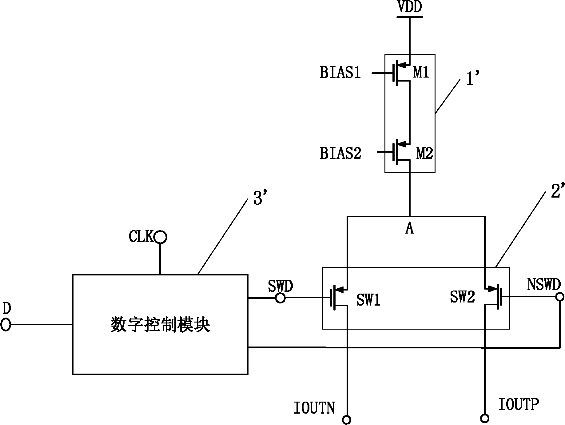
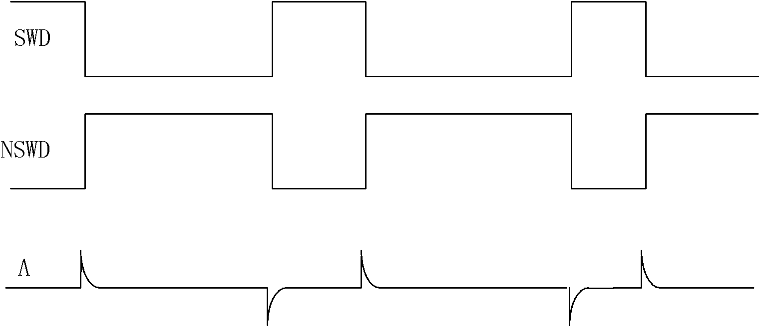
[0003] In the digital-to-analog converter of the current steering, the most critical is the output module, which is composed of a current source and a switch; generally speaking, the structure diagram of the current source switch circuit is as follows figure 1 As shown, the current source module 1' is composed of MOS tubes M1 and M2, the switch module 2' is composed of switch tubes SW1 and SW2, and the input signals SWD and NSWD of the switch tubes SW1 and SW2 are generated by the digital control module 3'. The switching tubes SW1 and SW2 in the module 2' turn on and off very quickly, resulting in the potential of the common source point A of the switch as figure 2 The fluctuation shown in the figure causes the output signal IOUTP and IOUTN to fluctuate, which leads to serious output harmonic distortion. The situation is even more serious in high-speed circuits close to the GHz level. This is one of the main non-ideal factors of high-speed digital-to-analog converters.

Method used


Image

  • Current source switching circuit for current rudder digital/analog converter
  • Current source switching circuit for current rudder digital/analog converter
  • Current source switching circuit for current rudder digital/analog converter

Examples


Embodiment Construction

[0014] Specific embodiments of the present invention will be described in detail below with reference to the accompanying drawings.

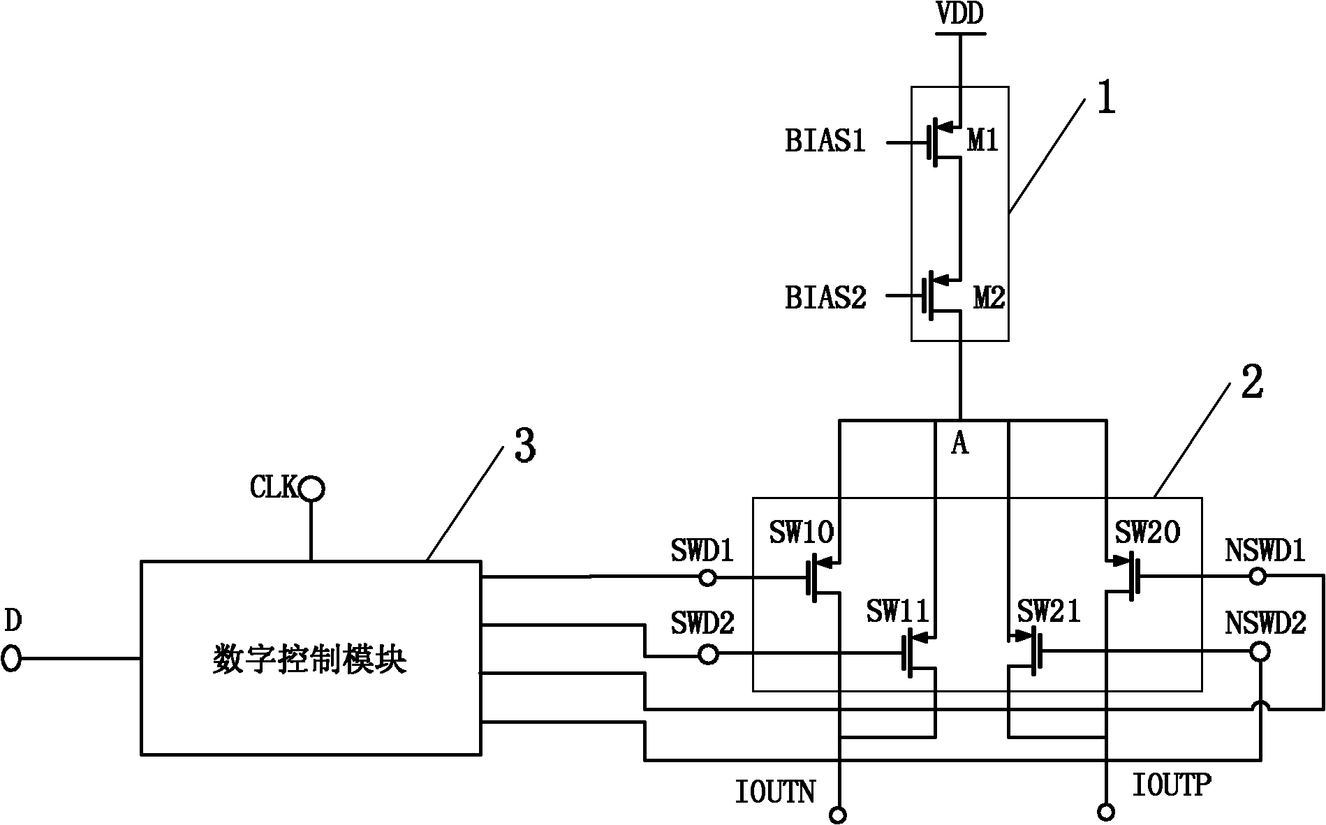
[0015] see image 3 , Figure 4 , the present invention, namely a current source switch circuit for a current rudder digital-to-analog converter, includes a current source module 1, a switch module 2 and a digital control module 3, wherein,

[0016] The current source module 1 includes a first MOS transistor M1 and a second MOS transistor M2, wherein the source of the first MOS transistor M1 is connected to the external power supply VDD, the drain thereof is connected to the source of the second MOS transistor M2, and the second MOS transistor M1 The drain of the transistor M2 is connected to the switch module 2, and the gates of the first MOS transistor M1 and the second MOS transistor M2 respectively receive the external first bias signal BIAS1 and the second bias signal BIAS2;

[0017] The digital control module 3 receives a digital signal ...


PUM


Abstract

The invention relates to a current source switching circuit for a current rudder digital / analog converter. The current source switching circuit comprises a current source module, a switching module and a digital control module, wherein the switching module is connected with the current source module, the switching module comprises a first switching tube, a second switching tube, a third switching tube and a fourth switching tube, source electrodes of the four switching tubes are connected to the current source module, grid electrodes of the fours switching tubes are respectively used for receiving a first control signal, a second control signal, a third control signal and a fourth control signal output by the digital control module, a drain electrode of the second switching tube is connected with a drain electrode of the first switching tube and outputs a first output signal, and a drain electrode of the fourth switching tube is connected with a drain electrode of the third switching tube and outputs a second output signal. In the invention, through the alternating conduction between two groups of switching tubes, the dynamic characteristic of the digital to analog converter is improved, and the high-speed and high-precision current rudder analog / digital converter is realized.

Description

technical field [0001] The present invention relates to an integrated circuit, in particular to a current source switch circuit for a current steering digital-to-analog converter. Background technique [0002] In analog integrated circuits or in interface circuits, the digital-to-analog conversion module is a very common functional module used to convert digital signals into analog signals, especially in integrated circuits with a precision of 16bit and above, which are now developed to the GHz level. At present, the structures mainly adopted are digital-to-analog converters in the form of current rudders to realize the above functions. [0003] In the digital-to-analog converter of the current rudder, the most important thing is the output module, which is composed of a current source and a switch. Generally speaking, the structure diagram of the current source switch circuit is as follows figure 1 As shown, the current source module 1' is composed of MOS transistors M1 an...

Claims


Application Information

Patent Timeline
Patent Type & Authority Applications(China)
IPC IPC(8): H03M1/66
Inventor 袁文师
Owner SHANGHAI BEILING
Learn More