
Movable oil pipe box for oil/water well operation

A mobile, oil pipe technology, applied in the direction of drilling pipe, casing, drilling equipment, etc., can solve the problems that affect the physical and mental health of operators, affect the environmental quality of mining areas, and high labor intensity of workers, so as to achieve high labor intensity of workers and improve the working environment , the effect of reducing the cost of measurement

Inactive Publication Date: 2011-08-10
胜利油田泰峰机电有限责任公司
View PDF7 Cites 16 Cited by
  • Summary
  • Abstract
  • Description
  • Claims
  • Application Information

AI Technical Summary

Problems solved by technology

[0002] At present, in oil field operations, the oil pipes are generally placed on the surface of the well site nearby, which takes up a lot of space, makes it difficult to move the oil pipes, has high labor intensity for workers, and presents potential safety hazards. In addition, there are waste liquids and pipe rods returned to the ground from oil and water wells. The oily sewage carried into the well site not only seriously affects the physical and mental health of the operators, but also affects the environmental quality of the mining area
In the process of running oil pipes into oil and water wells, in order to accurately reach the design depth of the pipe string, the workover workers need to measure the length of the oil pipes one by one. The workload is heavy and the measurement error is large, resulting in a low workover success rate.

Method used


Image

  • Movable oil pipe box for oil/water well operation
  • Movable oil pipe box for oil/water well operation
  • Movable oil pipe box for oil/water well operation

Examples


Embodiment Construction

[0017] In order to further disclose the technical solutions of the present invention, the following will be described in detail through examples in conjunction with the accompanying drawings:

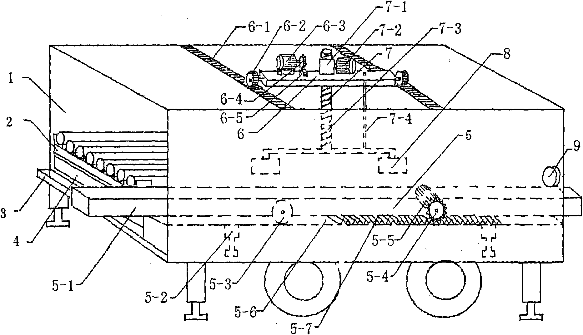
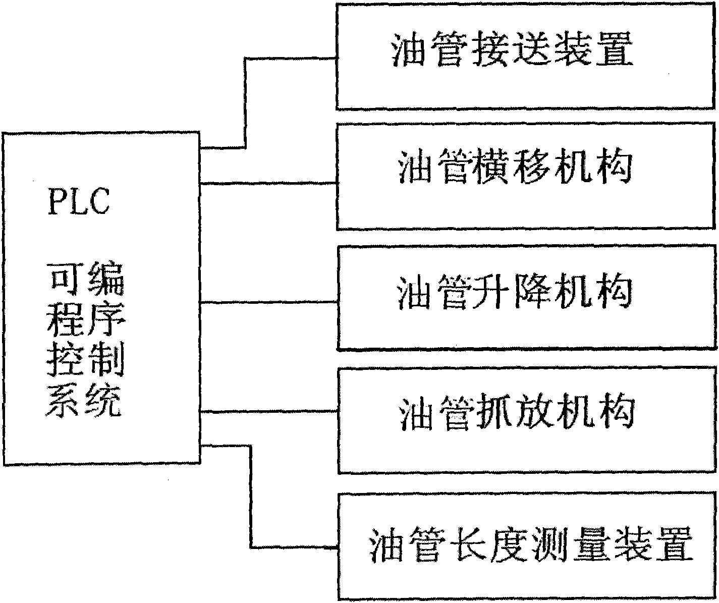
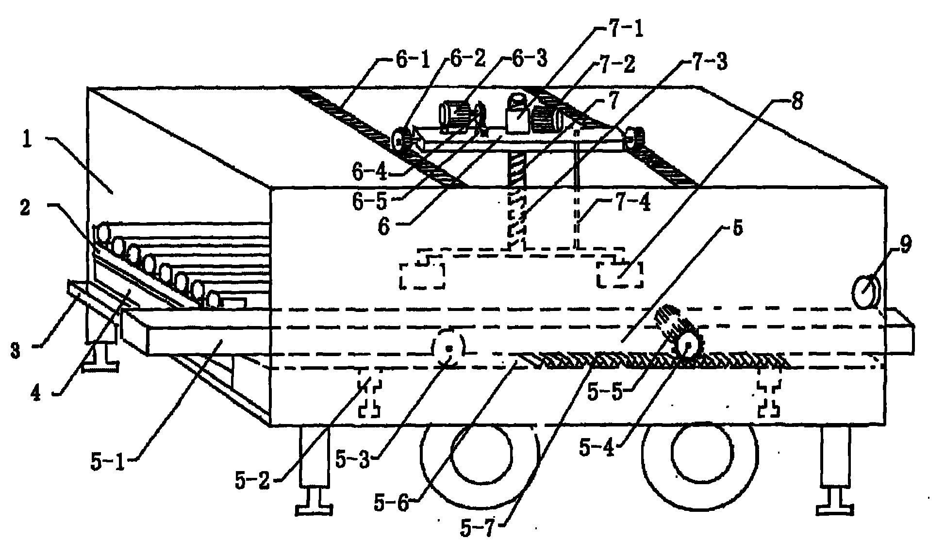
[0018] Such as figure 1 , 2 As shown, the operation mobile tubing box is a kind of oil and water well operation storage pipe device, which includes a tubing box 1, a tubing support 2, a trailer chassis 3, a sewage tank 4, a tubing pick-up device 5, a mobile platform 5-1, Lifting hydraulic cylinder 5-2, mobile platform driven wheel 5-3, gear 5-4, motor 5-5, bottom plate 5-6, rack 5-7, oil pipe traverse mechanism 6, traverse rack 6-1, Traversing gear 6-2, traverse motor 6-3, driving gear 6-4, driven gear 6-5, oil pipe lifting mechanism 7, lifting turbine 7-1, lifting motor 7-2, lifting worm 7-3 , guide rod 7-4, oil pipe pick-and-place mechanism 8, oil pipe length measuring device and PLC (programmable logic controller) system 9.

[0019] The oil pipe box is set as a rectangle, and is c...


PUM


Abstract

The invention discloses a movable oil pipe box for oil / water well operation. The movable oil pipe box comprises a trailer chassis, an oil pipe box, an oil pipe bracket, a sewage accumulating pool, an oil pipe oscillating mechanism, an oil pipe elevating mechanism, an oil pipe gripping mechanism, an oil pipe receiving and conveying device, an oil pipe length measuring instrument and a PLC (Programmable Logic Controller) system and is characterized in that the oil pipe box is rectangular and consists of a left part and a right part; the oil pipe bracket is arranged at the middle lower part of the left part; the sewage accumulating pool is arranged at the lower part of the left part; the oil pipe receiving and conveying device capable of extending inwards and outwards is arranged at the lower part of the right part; the oil pipe length measuring instrument is arranged at an inwardly extending opening of the oil pipe or the upper part of the back end of the oil pipe receiving and conveying device; the top middle part of the oil pipe box is provided with an oil pipe traversing mechanism; the oil pipe traversing mechanism is provided with the oil pipe elevating mechanism; the oil pipe gripping mechanism is arranged at the lower end of the oil pipe elevating mechanism; the oil pipe box is arranged on the trailer chassis; and the oil pipe receiving and conveying device, the oil pipe traversing mechanism, the oil pipe elevating mechanism and the oil pipe gripping mechanism are controlled by using the PLC system.

Description

technical field [0001] The invention relates to a storage and release oil pipe device for oil and water well operations, in particular to a mobile oil pipe box for oil and water well operations that can realize the functions of automatically picking up and sending oil pipes, measuring the length of the oil pipes and arranging the oil pipes. Background technique [0002] At present, in oil field operations, the oil pipes are generally placed on the surface of the well site nearby, which takes up a lot of space, makes it difficult to move the oil pipes, has high labor intensity for workers, and presents potential safety hazards. In addition, there are waste liquids and pipe rods returned to the ground from oil and water wells. The oily sewage carried into the well site not only seriously affects the physical and mental health of the operators, but also affects the environmental quality of the mining area. In the process of running oil pipes into oil and water wells, in order t...

Claims


Application Information

Patent Timeline
Patent Type & Authority Applications(China)
IPC IPC(8): E21B19/00E21B19/14
Inventor 亓和平刘超牟绍平李鹏马伟德于奥成宋玉全
Owner 胜利油田泰峰机电有限责任公司
Learn More