Cutting method for adjusting crystal orientation excursion by rotating single crystal rod

A cutting method and technology for single crystal rods, which are used in fine working devices, stone processing equipment, manufacturing tools, etc., can solve the problems of large size deviation of silicon wafer mechanical indicators, affecting the quality of slices and yield, and improve mechanical indicators. , the effect of improving the yield

Inactive Publication Date: 2011-08-17
浙江普通电子股份公司
View PDF6 Cites 11 Cited by
  • Summary
  • Abstract
  • Description
  • Claims
  • Application Information

AI Technical Summary

Problems solved by technology

This method cannot be completed on a multi-wire cutting machine. It can only be completed by using a bonding device that directional raises the y-axis. In this way, when the wire cuts into the ingot, the run...

Method used


Image

  • Cutting method for adjusting crystal orientation excursion by rotating single crystal rod
  • Cutting method for adjusting crystal orientation excursion by rotating single crystal rod
  • Cutting method for adjusting crystal orientation excursion by rotating single crystal rod

Examples


Embodiment Construction

[0008] The present invention will be further described below.

[0009] 1. Derivation of calculation formula:

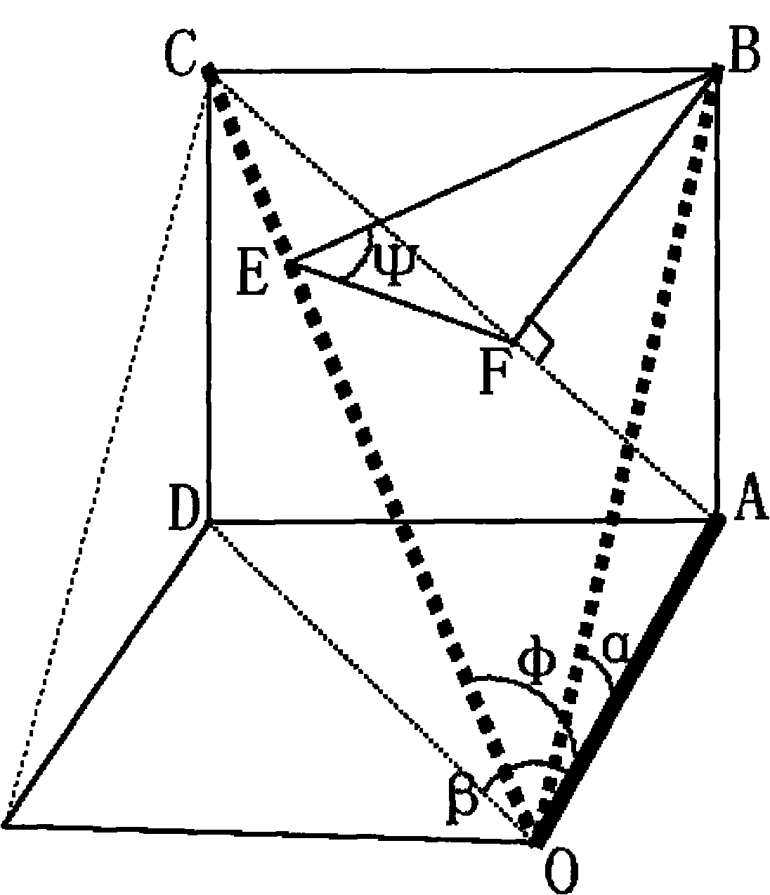
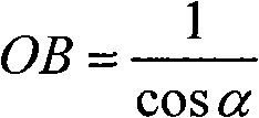
[0010] refer to figure 1 , let the single crystal rod length Radial longitudinal deflection angle ∠AOB=α, radial lateral deflection angle ∠AOD=β, radial plane adjustment angle ∠AOC=φ, silicon standard surface rotation angle ∠BEF=ψ. Among them, AOD is the initial cutting platform surface, AOC is the final cutting platform surface, BOC is the single crystal ingot standard surface, ABC is the blade cutting surface, is the cutting direction. The initial monocrystalline silicon radial direction is The adjusted radial direction is

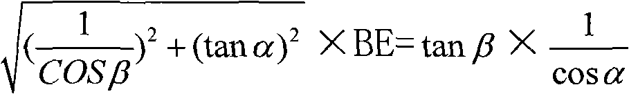
[0011] Then, (1) AB=tanα AD=tanβ

[0012] but AC = BC 2 + AB 2 = ( tan β ) 2 + ...


PUM


Abstract

The invention relates to a cutting method for adjusting crystal orientation excursion by rotating a single crystal rod. In the cutting method, during sticking of the single crystal rod, a reference surface is towards the upside and is parallel to a sticking steel plate; the horizontal excursion direction of the crystal rod is kept to the right; then the crystal orientation excursion of the crystal rod on an x-axis and a y-axis are tested; the excursion and the rotation angle of the crystal rod are calculated according to a vectorial principle; the y-axis is kept still horizontally and is adjusted through the rotation angle so as to obtain correct crystal orientation excursion. When the cutting method is adopted, the crystal rod is kept still horizontally on the y-axis through the rotation of the crystal rod to a certain angle and a certain direction; and excursion is only implemented on the x-axis to complete the crystal orientation excursion cutting. The cutting method not only is simple and easy, but also can improve the mechanical indexes of silicon wafer machinery; meanwhile, the cutting method greatly improves the yield of the cutting wafers of the crystal orientation excursion crystal rod.

Description

technical field [0001] The invention relates to a cutting method for adjusting crystal direction deviation by rotating a single crystal rod. Background technique [0002] Usually, the cutting of the single crystal rod adopts the positive crystal direction cutting, and the crystal direction error shall not affect the device characteristics. However, according to the silicon wafer epitaxial process requirements of integrated circuit substrates, many customers require that the silicon wafers provided be cut at a deviation of 4±0.5° from the nearest <110> plane parallel to the main reference plane. At the same time, the < The silicon wafer with 111> crystal orientation is sometimes required to be cut at 2°-4° to the <111> crystal orientation in the epitaxial process. According to the original cutting method, while the left and right angles are shifted on the x-axis in the horizontal direction, the up-down angle adjustment is performed on the y-axis in the vert...

Claims


Application Information

Patent Timeline
IPC IPC(8): B28D5/00
Inventor 余俊军吴志锋汪贵发吾勇军鲍庆梅陈锋
Owner 浙江普通电子股份公司
Why Eureka
Try Eureka