
Interlocking control system for falling, floating and depth sounding of main winch of rotary drilling rig

A technology of rotary drilling rig and control system, which is applied to the automatic control system of drilling, drilling equipment, earth-moving drilling, etc. Operation Intensity, Effect of Reducing Operation Intensity

Inactive Publication Date: 2011-08-17
徐州博汇东明机械制造有限公司
View PDF5 Cites 15 Cited by
  • Summary
  • Abstract
  • Description
  • Claims
  • Application Information

AI Technical Summary

Problems solved by technology

The current problem is that during the lowering process of the drill pipe of the rotary drilling rig, the control of the falling of the main coil is realized by controlling the hydraulic main valve to form a pressure difference between the A and B ports of the main coil motor. Fast; the floating and falling drill pipe of the main coil is to conduct the A and B ports of the motor of the main coil, and the motor rotates under the tension of the drill pipe's own weight. Due to the addition of a throttle hole, the falling speed of this method is relatively slow. It can only be used when the bucket is drilling in the hole
In the process of lowering the drill pipe, the driver can easily put more drill pipes to loosen the wire rope, causing the load of the wire rope to change sharply, deform, rotate, etc., thus reducing the service life of the wire rope. The staff also need to manually open the main volume and the float switch
Therefore, the driver needs to be extra careful when lowering the drill pipe, which increases the difficulty of operation

Method used


Image

  • Interlocking control system for falling, floating and depth sounding of main winch of rotary drilling rig
  • Interlocking control system for falling, floating and depth sounding of main winch of rotary drilling rig

Examples


Embodiment Construction

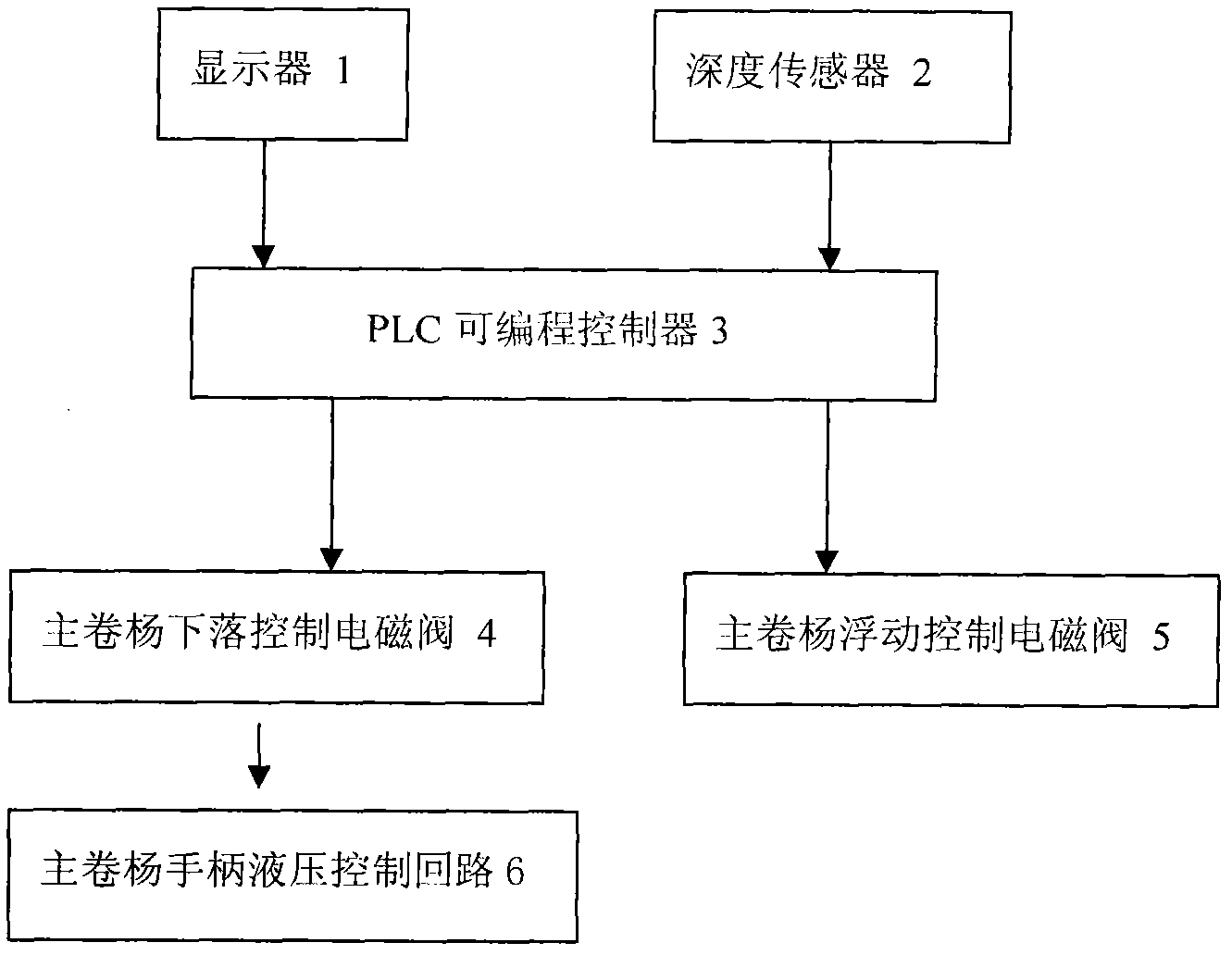
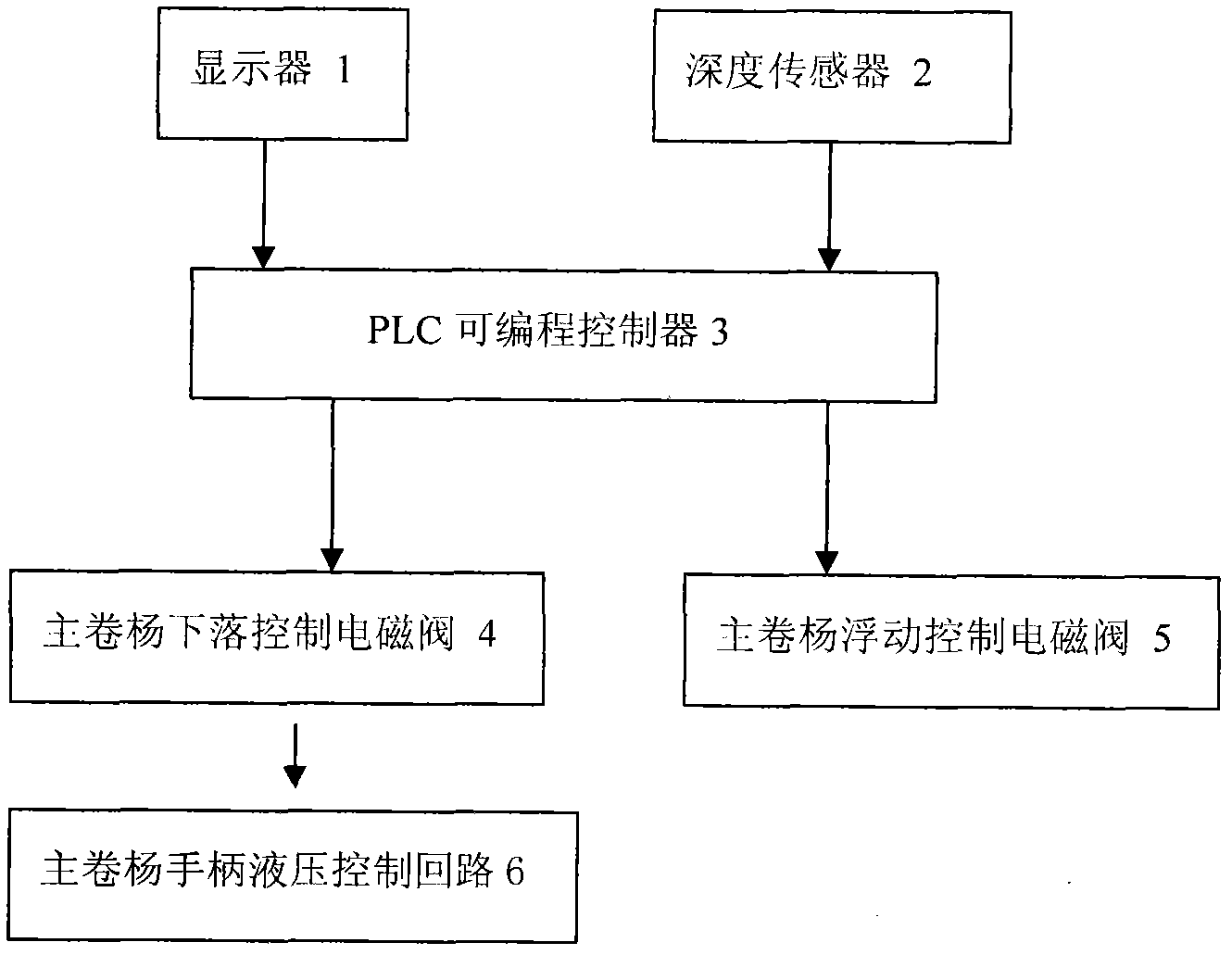
[0011] Such as figure 1 As shown, the control system of the main winch falling, main winch floating and sounding interlocking of the rotary drilling rig includes a central processing unit 3 on the rotary drilling rig for receiving and processing data and output control, and the central processing unit 3 adopts PLC Programmable Controllers. It is connected with the central processing unit 3 and is used for real-time online display of the drilling depth and the display 1 of various prompt information. The display 1 adopts a color display and is installed in the cab; the display 1 and the PLC programmable controller 3 are connected through the CANBUS bus. The depth-sounding sensor 2 that detects the change of the depth of the drill bit is connected with the central processing unit 3; the depth-sounding sensor 2 adopts an encoder or a proximity switch. The main coil floating control solenoid valve 5 connected with the central processing unit 3; the main coil falling control solen...


PUM


Abstract

The invention discloses an interlocking control system for falling, floating and depth sounding of a main winch of a rotary drilling rig, and belongs to an electro-hydraulic interlocking control mechanism. The interlocking control system comprises a central processing unit (CPU), a display connected with the CPU, a depth sounding sensor and a main winch floating control solenoid valve; and a main winch falling control solenoid valve and the CPU which are connected together are serially connected on a hydraulic handle control circuit for main winch falling for the rotary drilling rig. In the invention, when lowering depth of a drill bit is close to depth of a bore hole, the CPU stops outputting a control signal to a switch solenoid valve so as to cut off a pressure control oil circuit which causes falling of the main winch, and meanwhile the CPU outputs a control signal to automatically control main winch floating, which prevents a steel wire rope from being loosen. The interlocking control system has the beneficial effects that application range of equipment is enlarged, construction risk of a user is lowered, and operating strength of a driver is greatly reduced; and the interlocking control system has the advantages of simple structure, reliable performance and low cost, and is convenient in operation.

Description

technical field [0001] The invention relates to an electro-hydraulic control mechanism, in particular to a control system for the interlocking of falling, floating and sounding of the main winch of a rotary drilling rig. Background technique [0002] With the continuous acceleration of my country's infrastructure construction, rotary drilling rigs, as an emerging product in the construction machinery industry, have become the most ideal construction machinery for hole-forming operations in high-speed rail, elevated, and building foundation projects. Rotary drilling rigs are characterized by high efficiency, high quality, and environmental protection, and are the fastest-growing leading products of piling machinery. The current problem is that during the lowering process of the drill pipe of the rotary drilling rig, the control of the falling of the main coil is realized by controlling the hydraulic main valve to form a pressure difference between the A and B ports of the mai...

Claims


Application Information

Patent Timeline
IPC IPC(8): E21B44/00
Inventor 陈志王玉成徐适王从明董梅孙文孟晴刘玮
Owner 徐州博汇东明机械制造有限公司
Learn More