Continuously variable compression ratio engine and power output device thereof

An engine and compression ratio technology, applied in engine control, engine components, machines/engines, etc., can solve problems such as air distribution shock cooling and sealing engine body stability, cylinder bias pressure, and technical design difficulties of variable compression ratio

Inactive Publication Date: 2011-08-17
丛培伟
View PDF10 Cites 8 Cited by
  • Summary
  • Abstract
  • Description
  • Claims
  • Application Information

AI Technical Summary

Problems solved by technology

[0013] 2. Design Difficulties of Variable Compression Ratio Technology
[0020] 3. There is an eccentric support sleeve on the piston pin. The core problem is that the eccentric support sleeve on the piston pin makes the connecting rod deviate too much from the cylinder axis, which causes the cylinder to wear out or even pull the cylinder; the design of the control mechanism is difficult. Auxiliary linkage controls are not a good solution
[0023] 6. The eccentric sleeve is added to the crank pin. This method can realize variable compression ratio, but the friction energy consumption is large.
The core of this mechanism is the controllable swing of the cylinder, and the space angle of the swing of the cylinder is very large, so that the piston axis at the top dead center deviates from the radial direction of the crankshaft, thus causing the cylinder bias problem
In addition, the mechanism mechanism is complex, the control actuation force and maintenance force are large, and it also involves the problem of gas distribution shock, cooling and sealing problems, and the stability of the engine body.

Method used


Image

  • Continuously variable compression ratio engine and power output device thereof
  • Continuously variable compression ratio engine and power output device thereof
  • Continuously variable compression ratio engine and power output device thereof

Examples


Embodiment 1

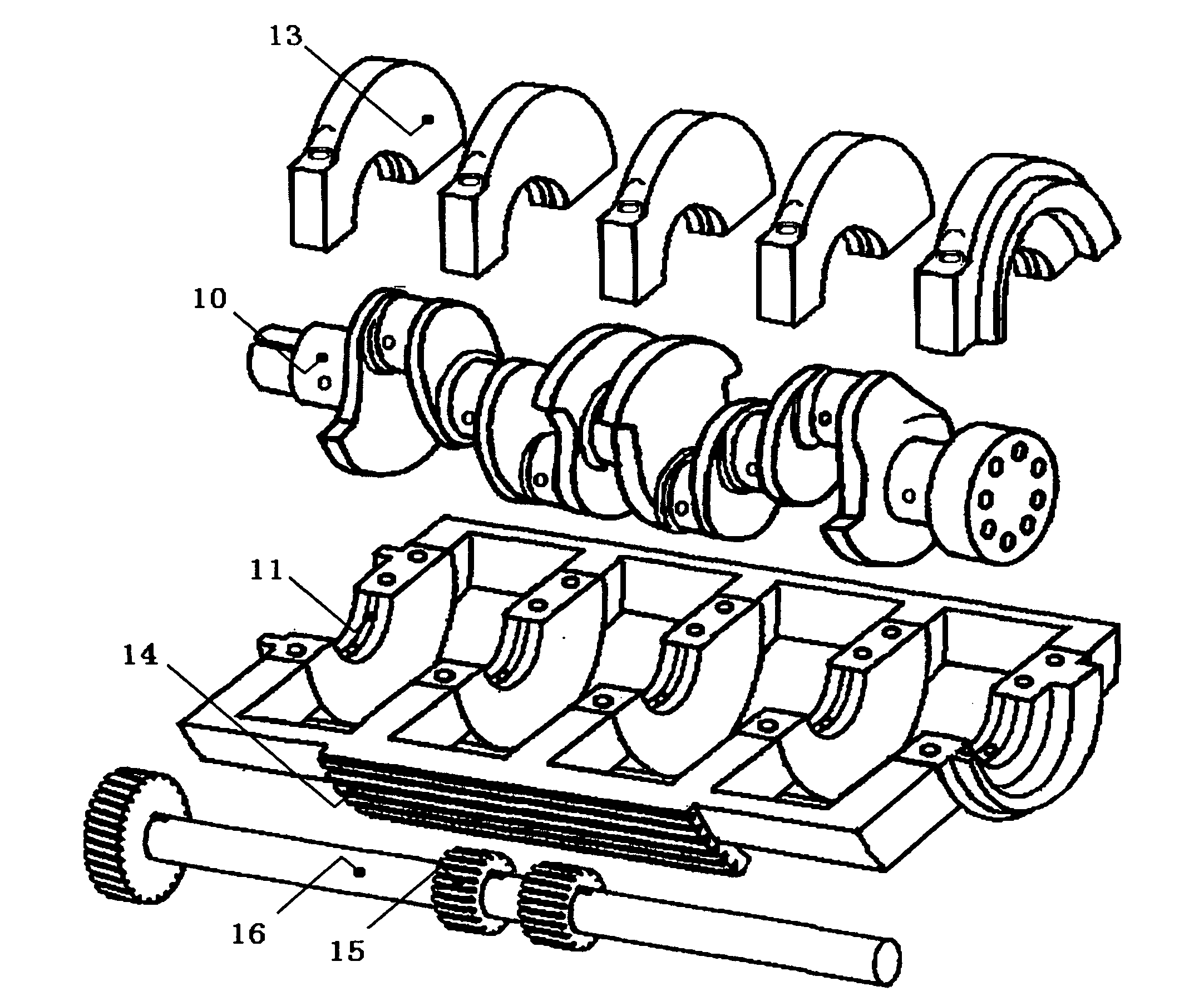
[0078] figure 1 This is an exploded three-dimensional view of the main components of the variable compression ratio engine of Embodiment 1. It can roughly understand the three-dimensional shape of some components, including the crankshaft 10, the crankshaft bearing cap 13, the crankshaft deflection support body 11 and its sector gear 14, the control gear 15 and Control axis 16.

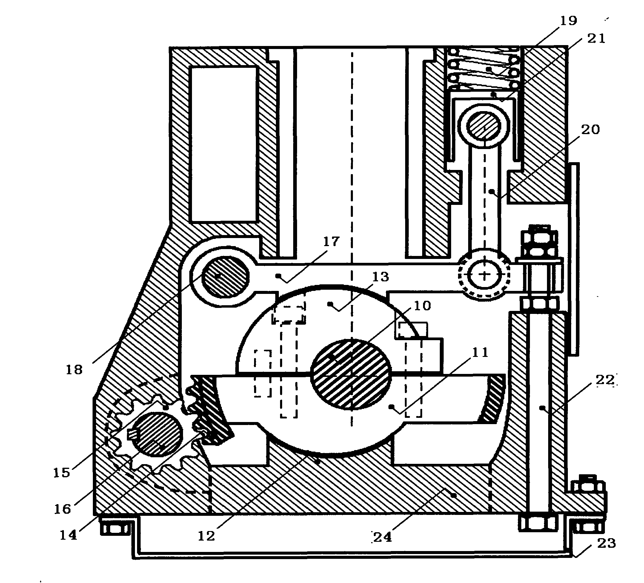
[0079] figure 2 It is a radial cross-sectional view of the first-type continuously variable compression ratio engine of Embodiment 1, which mainly includes the crankshaft 10, the crankshaft deflection support 11, the crankshaft bearing cover 13, the engine block 24, and the control drive mechanism. The control drive mechanism is divided into a switching maintenance part and an independent locking part according to its main functions. The switching maintenance part includes a control shaft 16 and its control gear 15, and the independent locking part includes a brake pressure plate 17 and a connection of t...

Embodiment 2

[0086] Figure 8 It is a radial cross-sectional view of the second type of continuously variable compression ratio engine used in Embodiment 2. It is easy to describe, and part of the radial cross section of the second type of continuously variable compression ratio engine shown is staggered. The space support of the crankshaft deflection support body 11 of the second type of continuously variable compression ratio engine is all borne by its outer arc-shaped end surface. The crankshaft bearing cover 13 can be provided without an outer arc-shaped end surface; because the crankshaft deflection support body 11 is very thick Therefore, only a single-sided connection is provided; because the upward force on the crankshaft deflection bracket 11 is not large, the slightly complicated control piston connecting rod mechanism is cancelled. The brake pressure plate is adjusted by the spring pad 19a and the adjusting screw 22, so that the crankshaft deflection bracket can be locked and rota...

Embodiment 3

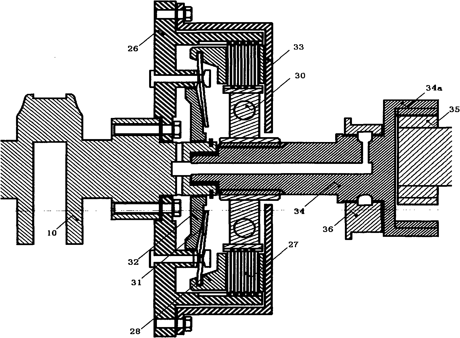
[0089] The variable compression ratio engine of the third embodiment is exactly the same as that of the first embodiment. The difference is that an eccentric clutch in which the power output device of the first embodiment is replaced by a torque converter is provided. Picture 10 It is a schematic diagram of the combination of the hydraulic torque converter and the active eccentric support sleeve of the third embodiment. The active eccentric support sleeve 36 a shown is disposed on the transmission input shaft 34. When the engine compression ratio is switched, the crankshaft 10, the torque converter 42, the transmission input shaft 34, and the active eccentric support sleeve 36a simultaneously perform eccentric rotation. The present invention requires that the eccentric support sleeve must be able to rotate. Therefore, for the torque converter 40 with flexible force coupling, an active eccentric support sleeve 36a is generally provided. Figure 7 Shown in A is a schematic diagra...


PUM


Abstract

The invention discloses a continuously variable compression ratio engine and a power output device thereof. The engine comprises a crankshaft, an integrated crankshaft deflection support body, a crankshaft bearing cover, a crankshaft timing gear part, a control driving mechanism, a flywheel, an eccentric clutch and a transmission input shaft, wherein the control driving mechanism has braking and locking functions. The original design thought is that: when the flywheel and the eccentric clutch are eccentrically rotated along with the crankshaft simultaneously, a difficult engine variable compression ratio problem is converted into an eccentric clutch designing problem. The engine and the device aim to completely solve the technical problems of variable compression ratio engines which make human beings troubled for nearly a century, and struggle for saving one third of energy in the world and returning a sustainable green environment to the world.

Description

Technical field [0001] The invention relates to a continuously variable compression ratio engine and a power output device thereof, which is used for enabling the compression ratio of the engine to be continuously variable according to the requirements of specific working conditions. Background technique [0002] Engine designers know that continuously variable compression ratio technology and continuously variable valve lift technology are the two most cutting-edge technical problems of reciprocating engines. It can be said that human design of engines is developed around these two major problems, or the engine Most of the new technologies are continuously variable compression ratio technology and continuously variable valve lift technology compensation technology. At present, with the perfect solution of the continuous variable valve lift technology of the engine, the continuous variable compression ratio technology that has plagued the engine industry for nearly a century is a...

Claims


Application Information

Patent Timeline
Patent Type & Authority Applications(China)
IPC IPC(8): F01L13/08F02B61/06F02F7/00F02F1/00F02D15/00
Inventor 丛培伟
Owner 丛培伟
Why Eureka
Try Eureka