Mixed type driving and driven magnetic suspension bearing

A magnetic suspension bearing and hybrid technology, applied in the field of magnetic bearings, can solve the problems of large volume, high weight, large temperature rise, etc., and achieve the effects of reducing ampere turns, volume, loss and temperature rise.

Active Publication Date: 2011-08-17
GREAT POWER CO LTD
View PDF3 Cites 22 Cited by
  • Summary
  • Abstract
  • Description
  • Claims
  • Application Information

AI Technical Summary

Problems solved by technology

[0004] In order to solve the problems of large volume, high weight and high temperature rise in the existing magnetic suspension bearings based on the working principle of electromagnets, the present invention proposes an active and passive hybrid magnetic suspension bearing

Method used


Image

  • Mixed type driving and driven magnetic suspension bearing
  • Mixed type driving and driven magnetic suspension bearing
  • Mixed type driving and driven magnetic suspension bearing

Examples


specific Embodiment approach 1

[0009] Specific Embodiments 1. The active and passive hybrid magnetic suspension bearing described in this embodiment includes a stator, a rotor and an air gap.

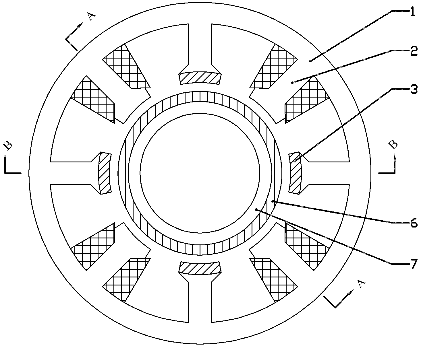
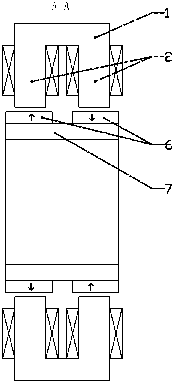
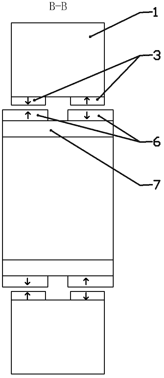
[0010] The rotor includes a rotor magnetically conducting yoke 7 and a rotor permanent magnet 6. The rotor magnetically conducting yoke 7 is cylindrical, and two annular rotor permanent magnets 6 are axially distributed on the rotor yoke 7. On the outer surface, the magnetization direction of each annular rotor permanent magnet 6 is radial magnetization, and the magnetization directions of the two annular rotor permanent magnets 6 are opposite;

[0011] The stator includes a stator core 1, a radial force control winding and a stator permanent magnet 3. The stator core 1 is cylindrical, and the inner surface of the cylindrical stator core 1 is grooved in the axial direction, and formed on the inner side of the stator core 1. 4n stator teeth, where n is a natural number greater than 1, on the inner surface of the first...

specific Embodiment approach 2

[0013] Specific embodiment 2. This embodiment is a further limitation of the active and passive hybrid magnetic suspension bearing described in specific embodiment 1. The rotor in the active and passive hybrid magnetic suspension bearing described in this embodiment also includes a rotor protection sleeve 9 , see Figure 11 As shown, the rotor protective sleeve 9 is cylindrical, and is fixedly sleeved on the outer surface of the rotor permanent magnet 6 .

[0014] The rotor protective sleeve 9 added in this embodiment is made of high-strength material to protect the rotor. The rotor protective sleeve 9 is a thin-walled cylinder, and the wall thickness of the round tube is determined according to the diameter and rotational speed of the rotor, generally 0.5-4mm.

specific Embodiment approach 3

[0015] Specific Embodiment Three. This embodiment is a further limitation of the active and passive hybrid magnetic suspension bearing described in specific embodiment one or two. In the rotor of the active and passive hybrid magnetic suspension bearing described in this embodiment, two On the outer surface of the rotor magnetically conducting yoke cylinder 7 between the annular rotor permanent magnets 6, an axially magnetized annular rotor permanent magnet 4 is also fixed, and the axially magnetized annular permanent magnet The direction of magnetization is from the inwardly magnetized annular rotor permanent magnet 6 to the outwardly magnetized annular rotor permanent magnet 6, see Figure 4 and Figure 5 shown.

[0016] In this embodiment, an axially magnetized annular rotor permanent magnet 4 is added in the rotor, and the axially magnetized annular rotor permanent magnet 4 is axially magnetized, which is different from the original Two radially magnetized annular rotor ...


PUM


Abstract

The invention relates to a mixed type driving and driven magnetic suspension bearing, which solves the problems of large volume, heavy weight and high temperature rise of the conventional magnetic suspension bearing. Two circular ring-like rotor permanent magnets are sleeved on an outer surface of a rotor magnetically-conductive yoke cylinder along axial direction; an inner surface of a stator iron core is grooved along the axial direction to form 4n stator teeth; two tile-shaped stator permanent magnets are fixedly adhered to the inner surfaces of the first, third, ..., and (4n-1)th stator teeth along the axial direction; the position of each stator permanent magnet corresponds to that of one of the circular ring-like rotor permanent magnets; the second, fourth, ..., and 4nth stator teeth are armature teeth in a double-teeth structure; a coil is wound on each tooth in the double-teeth structure; the coils on all armature teeth are connected in series to form a radial force control winding; and two coils on two teeth which are opposite by 180 degrees in circumference are connected in series in reverse direction to form a set of windings. By the invention, the dynamic response of the bearing is improved.

Description

technical field [0001] The invention relates to an active and passive hybrid magnetic suspension bearing, belonging to the technical field of magnetic bearings. Background technique [0002] Magnetic bearing, also known as active magnetic suspension bearing, is a new type of high-performance bearing without mechanical contact between the rotor and the stator. Compared with traditional ball bearings, sliding bearings and oil film bearings, magnetic suspension bearings use electromagnetic force to suspend the rotor in space, there is no mechanical contact between the stator and rotor, and the rotor can reach a very high speed, with small mechanical wear and energy consumption. Low noise, long life, no lubrication, no oil pollution, etc., especially suitable for special environments such as high speed, vacuum, and ultra-clean. It can be widely used in the fields of mechanical processing, turbomachinery, aerospace, petroleum and petrochemical, vacuum technology, energy, rotor d...

Claims


Application Information

Patent Timeline
Patent Type & Authority Applications(China)
IPC IPC(8): F16C32/04
CPCF16C32/0465F16C32/048
Inventor 寇宝泉周一恒吴太箭
Owner GREAT POWER CO LTD
Why Eureka
Try Eureka