Comprehensive heating system by using hot water based on fire pit

A comprehensive system and combustion pool technology, applied in heating systems, household heating, applications, etc., to achieve the effect of simple structure, low cost and good heating effect

Inactive Publication Date: 2011-08-17
DALIAN UNIV OF TECH
View PDF4 Cites 12 Cited by
  • Summary
  • Abstract
  • Description
  • Claims
  • Application Information

AI Technical Summary

Problems solved by technology

[0005] The technical problem to be solved by the present invention is to realize the reuse of agricultural waste in winter heating, solve the problem of the recycling of renewable

Method used


Image

  • Comprehensive heating system by using hot water based on fire pit
  • Comprehensive heating system by using hot water based on fire pit
  • Comprehensive heating system by using hot water based on fire pit

Examples


specific Embodiment approach 1

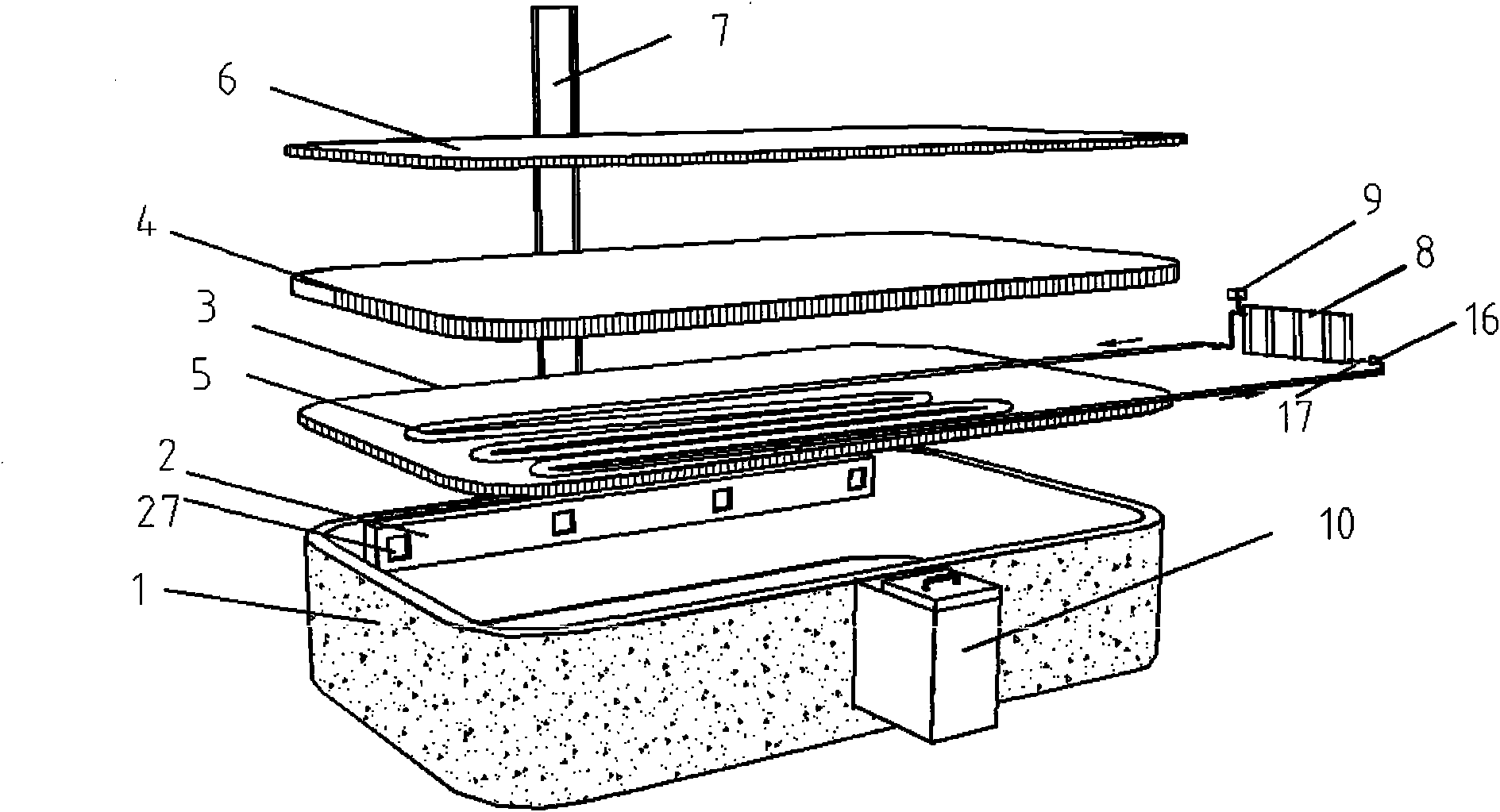
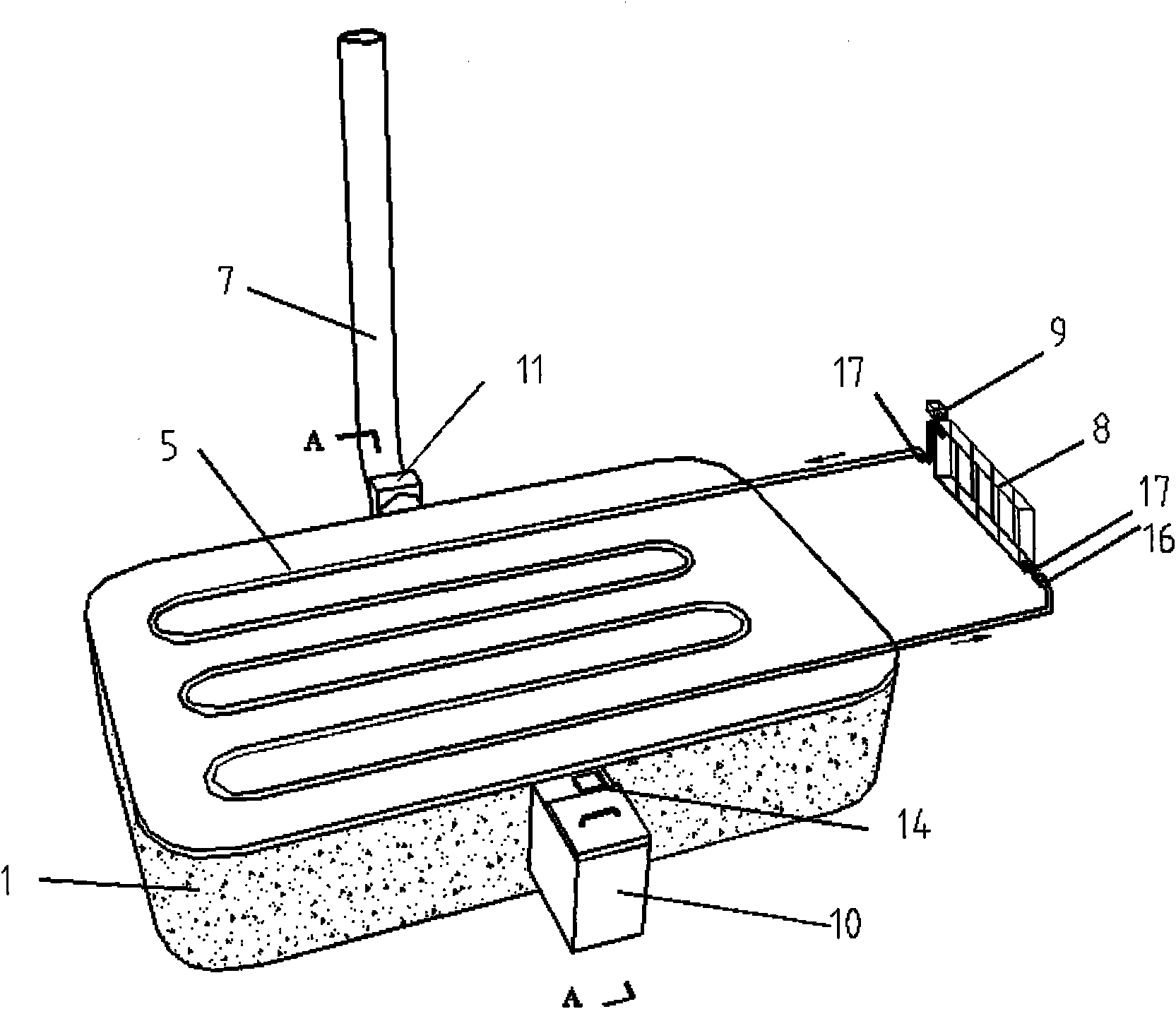
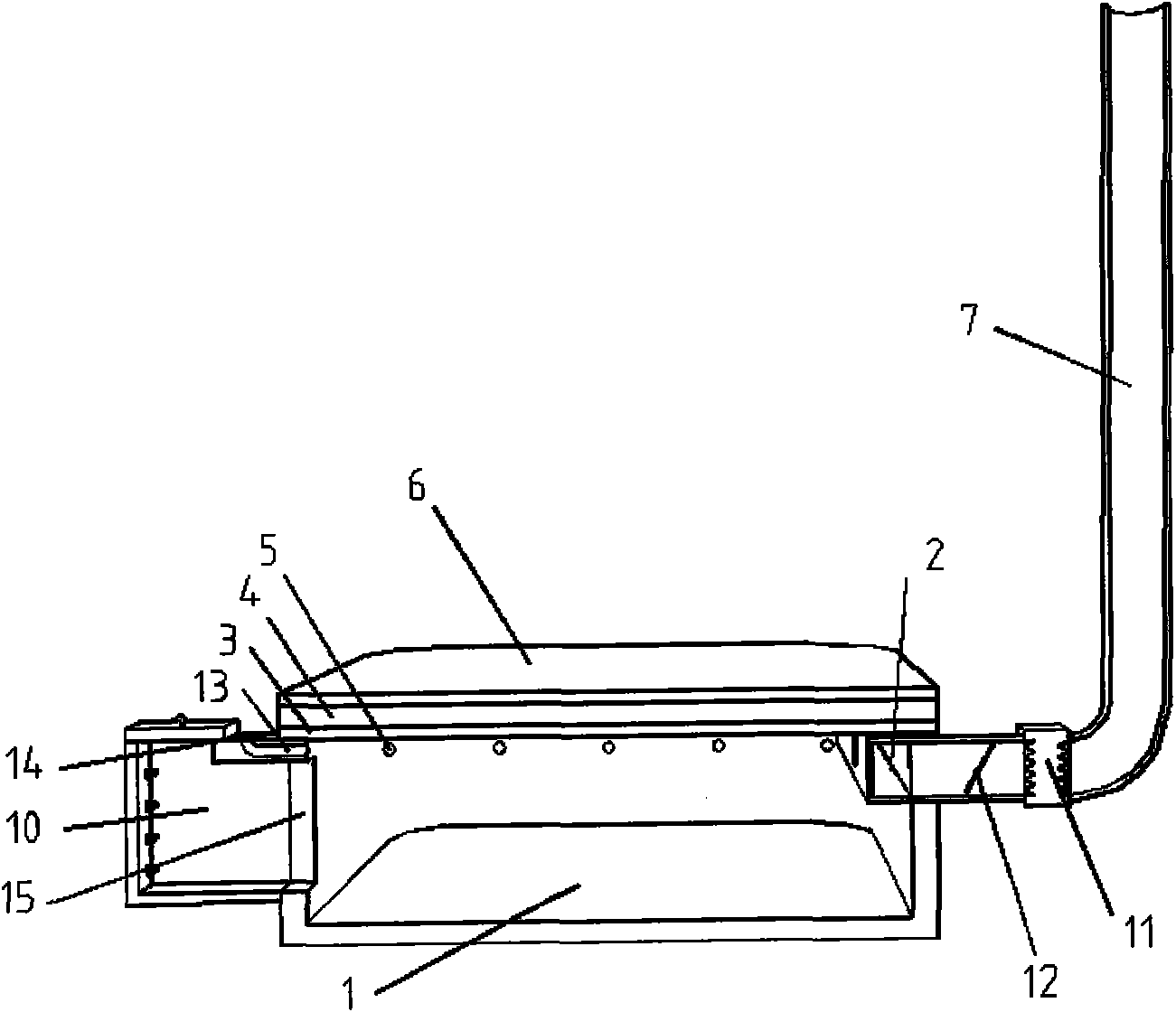
[0014] Specific implementation plan one: if Figure 1~2 As shown, the comprehensive heating system based on the use of hot water in the combustion pool is mainly composed of the main body of the combustion pool 1, the horizontal flue 2, the hot water coil 5, the vertical chimney 7, the radiator 8, the expansion tank 9, the filling port 10, and the flue gas filter device 11, smoke control valve 12 and other components. The main body of the fuel pool 1 is a rounded rectangle with a depth of 1.7 meters. The filling port 10 is located at the center of the front of the main body 1 of the fuel pool. Straight climbing ladder 26 is convenient for filling and overhaul. The entrance 15 of the combustion pool is sealed by a prefabricated concrete slab or a brick block, and can be opened and closed freely.

specific Embodiment approach 2

[0015] Specific implementation plan two: if Figure 1~4 As shown, the hot water coil 5 can be fixed under the cover plate of the combustion pool, between the cover plate 3 and the ground layer 6, and the hot water coil 5 is an iron pipe, which is connected with the radiator 8 outside the combustion pool to form a closed circuit, the flow in the hot water coil 5 is controlled by the regulating valve 17 and the water pump 16. The cover plate 3 is prefabricated with reinforced concrete, the ground layer 6 is a cement leveling layer, and the loess layer 4 can prevent the leakage of smoke.

specific Embodiment approach 3

[0016] Specific implementation plan three: if figure 2 As shown in ~ 5, the flue system is composed of a horizontal flue 2, several flue openings 27, a flue gas filter 11, and a vertical chimney 7. The horizontal flue 2 is located at the top of the inner wall at the back of the combustion pool main body 1 , below the combustion pool cover plate 3 , and consists of four symmetrical flue openings 27 . The flue gas is collected into the horizontal flue 2, purified by the flue gas filter 11, and discharged from the chimney 7. A flue gas control valve 12 is also provided at the bottom of the chimney, and the smoke exhaust volume is controlled by changing the angle of the flue gas control valve 12 .

[0017] Specific implementation plan four: as figure 1 As shown in ~5, after the fuel stalks, wood chips, corncobs, etc. in the main body of the combustion pool 1 are smoldering, the medium water in the hot water coil 5 is heated, and after the hot water transfers the heat through th...


PUM


Abstract

The invention provides a comprehensive heating system by using hot water based on a fire pit, and belongs to the technical field of resource reuse and building energy saving. The comprehensive heating system by using hot water based on the fire pit is characterized by consisting of the fire pit, a flue, a cover board, a loess layer, a hot water coiler, a heat dissipater, a flue, a feeding opening and the like; the hot water coiler is fixed under the cover board of the fire pit or pre-embedded into the loess layer; the heat dissipater is connected with the hot water coiler so as to form a closed loop; water in the hot water coiler is heated, and the heat is transferred and reused by the heat dissipater; and the smoke in the fire pit is collected through the horizontal flue and uniformly exhausted through a chimney. The comprehensive heating system has the advantages of using agricultural wastes to the largest extent, along with low cost, simple structure, good heating effect and the like, is suitable for large-area popularization, and can be applied to construction of houses in villages and small towns and industrial factories in nonconcentrated heating places.

Description

technical field [0001] The invention belongs to the technical field of resource reuse and building energy saving, and relates to a comprehensive system for heating with hot water based on a combustion pool. Background technique [0002] With the development of new rural construction, the energy consumption of coal-based commodities has increased sharply. In my country, heating energy consumption in northern villages and towns accounts for one-third of the total energy consumption of buildings in the country, which is the largest component of building energy consumption. There are many problems and difficulties in the central heating of northern industrial plants in winter due to large initial investment and operating costs, large temperature gradients, severe air stratification, and a lot of energy waste. But at the same time, rural areas in the north are burned every year due to a large amount of fuel such as straw and firewood that cannot be resettled. When burning straw ...

Claims


Application Information

Patent Timeline
IPC IPC(8): F24D15/02
CPCY02B30/12
Inventor 陈滨刘鸣张宝刚张雪妍朱佳音田维治谢艺强白淑鑫张瑞娜
Owner DALIAN UNIV OF TECH
Why Eureka
Try Eureka