
Portable detection device for detecting sighting line zero position of infrared sniperscope

A portable detection, infrared sighting technology, applied in the field of infrared sighting baseline zero position portable detection devices, can solve the problems of inability to move, inconvenient operation, heavy and other problems, and achieve the effects of easy debugging, simple operation and convenient use

Inactive Publication Date: 2011-08-17
CHANGCHUN UNIV OF SCI & TECH
View PDF0 Cites 13 Cited by
  • Summary
  • Abstract
  • Description
  • Claims
  • Application Information

AI Technical Summary

Problems solved by technology

The detection device is complicated in system, loose in structure, bulky and heavy, and cannot be moved. In other words, the device is not a special-purpose instrument, which is difficult to debug and inconvenient to operate. In addition, the detection efficiency is low and the accuracy is not high. Straight lenses are expensive

Method used


Image

  • Portable detection device for detecting sighting line zero position of infrared sniperscope
  • Portable detection device for detecting sighting line zero position of infrared sniperscope
  • Portable detection device for detecting sighting line zero position of infrared sniperscope

Examples


Embodiment Construction

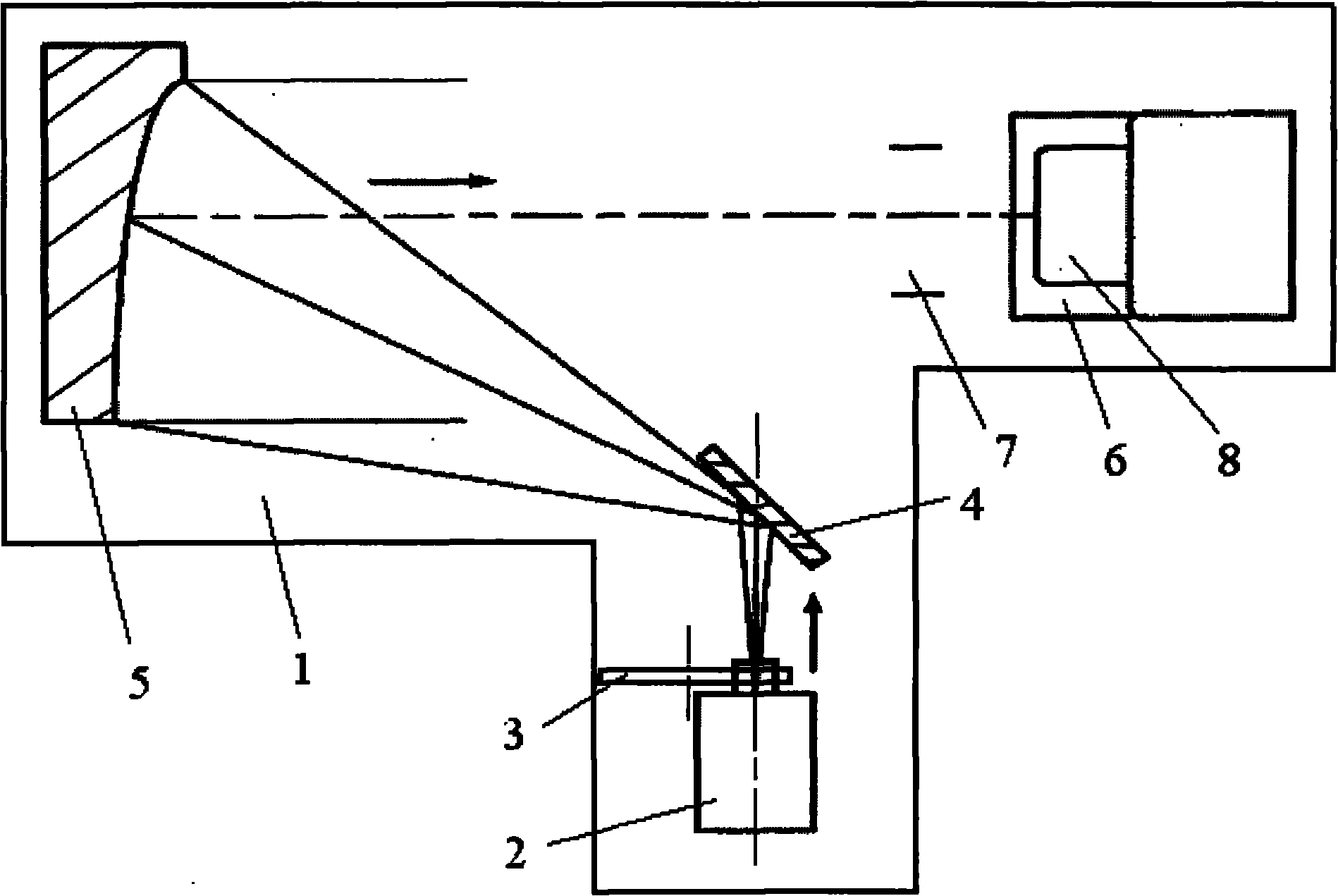
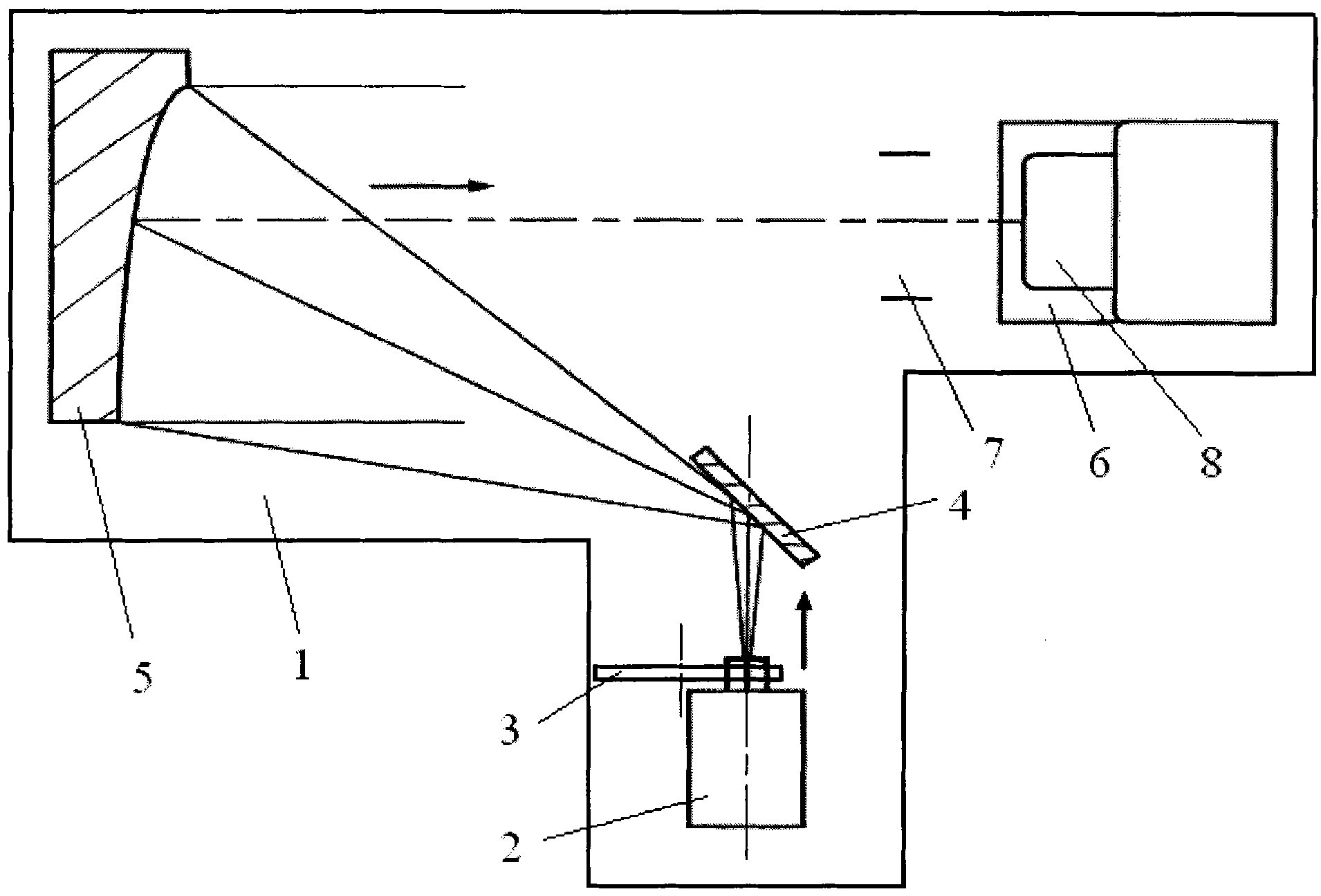
[0008] The present invention is implemented like this, see figure 1 As shown, the sealing cover is buckled on the base 1. The inside of the sealing cover is coated with black light-absorbing paint. Base 1 is a rigid body. The blackbody 2, the disc target 3, the plane reflector 4 and the off-axis parabolic reflector 5 are fixed on the base 1 and located in the sealed cover. The card holder 6 is fixed on the base 1 but is located outside the sealing cover, and an infrared window 7 is opened on the side wall of the sealing cover opposite to the card seat 6, and the infrared window 7 is an atmospheric window. Blackbody 2 is an electrothermal infrared light source, and the differential blackbody temperature control accuracy is 0.1°C. The plane reflector 4 and the off-axis parabolic reflector 5 are made of aluminum, which is not only light in weight, but also has a high reflectivity for mid- and far-infrared light of 8-14 μm. The focal length of the infrared collimator composed ...


PUM


Abstract

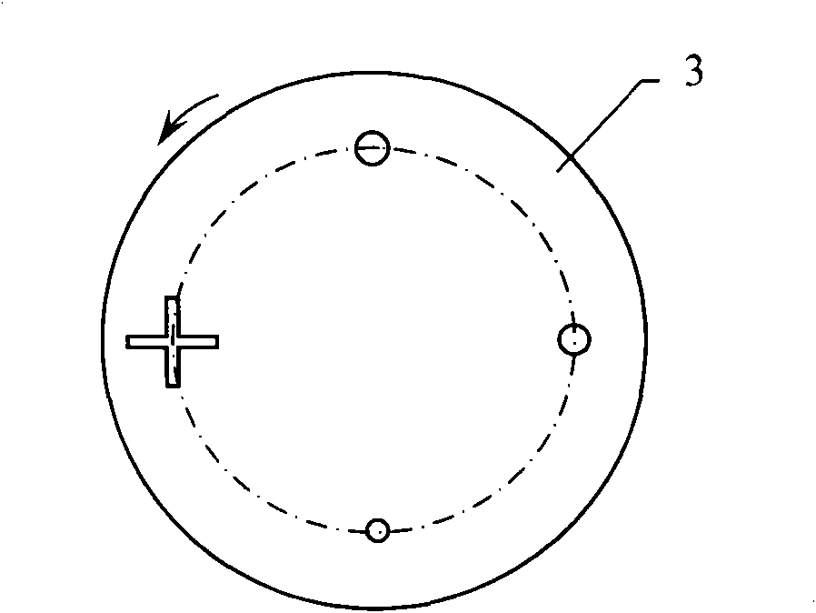
The invention discloses a portable detection device for detecting a sighting line zero position of an infrared sniperscope, and belongs to the technical field of infrared optics detection. The conventional detection device is not a shaped special instrument. The detection device provided by the invention is characterized in that: a sealed hood is fastened on a base; a black body, a round disc target, a planar reflector and an off-axis parabolic mirror are fixed on the base and positioned in the sealed hood; a buckling base is fixed on the base and positioned out of the sealed hood. An infrared window is formed on the lateral wall of the sealed hood and opposite to the buckling base; a cross slot hole and a plurality of different round holes are formed on the round disc target; and the centre of the cross slot hole and the centers of a plurality of round holes are positioned on the same circle of the round disc target. The off-axis parabolic mirror, the infrared window and the buckling base are sequentially arranged by taking the axis of parallel light reflected by a reflector on the off-axis parabolic mirror as an axis. The black body, the centre of the cross slot hole or the center of one of the plurality of round holes and the planar reflector are coaxially arranged on one side of the axis of the reflector on the off-axis parabolic mirror as an axis sequentially.

Description

technical field [0001] The invention relates to a portable detection device for the zero position of the aiming baseline of the infrared sight, which can be used to detect the zero position of the aiming baseline of the infrared sight on site, such as the production site of the infrared sight and the use site after leaving the factory, especially in the latter case It can be detected at any time, convenient and timely. The invention belongs to the technical field of infrared optical detection. Background technique [0002] The infrared sight is composed of an infrared imaging tube, a reticle, etc. It is used on a firearm and can aim at a target at night. Infrared sights are also used in medical treatment, fire protection, and industry, such as observing human inflammatory lesions, observing hidden fires or erosion of blast furnace walls. The infrared sight needs to be calibrated to aim at the zero baseline before leaving the factory. During use, due to the aging and vibra...

Claims


Application Information

Patent Timeline
IPC IPC(8): G01B11/00
Inventor 李永亮温彬安志勇曹维国肖作江李丽娟石利霞
Owner CHANGCHUN UNIV OF SCI & TECH
Learn More