Circuit arrangement and method for operation of discharge lamp

A technology for circuit devices and discharge lamps, which can be used in lighting devices, electric light sources, electrical components, etc., and can solve problems such as undesired power loss

Inactive Publication Date: 2011-08-17
OSRAM GMBH
View PDF4 Cites 5 Cited by
  • Summary
  • Abstract
  • Description
  • Claims
  • Application Information

AI Technical Summary

Problems solved by technology

However, this solution is undesirable in terms of power loss resulting from

Method used


Image

  • Circuit arrangement and method for operation of discharge lamp
  • Circuit arrangement and method for operation of discharge lamp
  • Circuit arrangement and method for operation of discharge lamp

Examples


Embodiment Construction

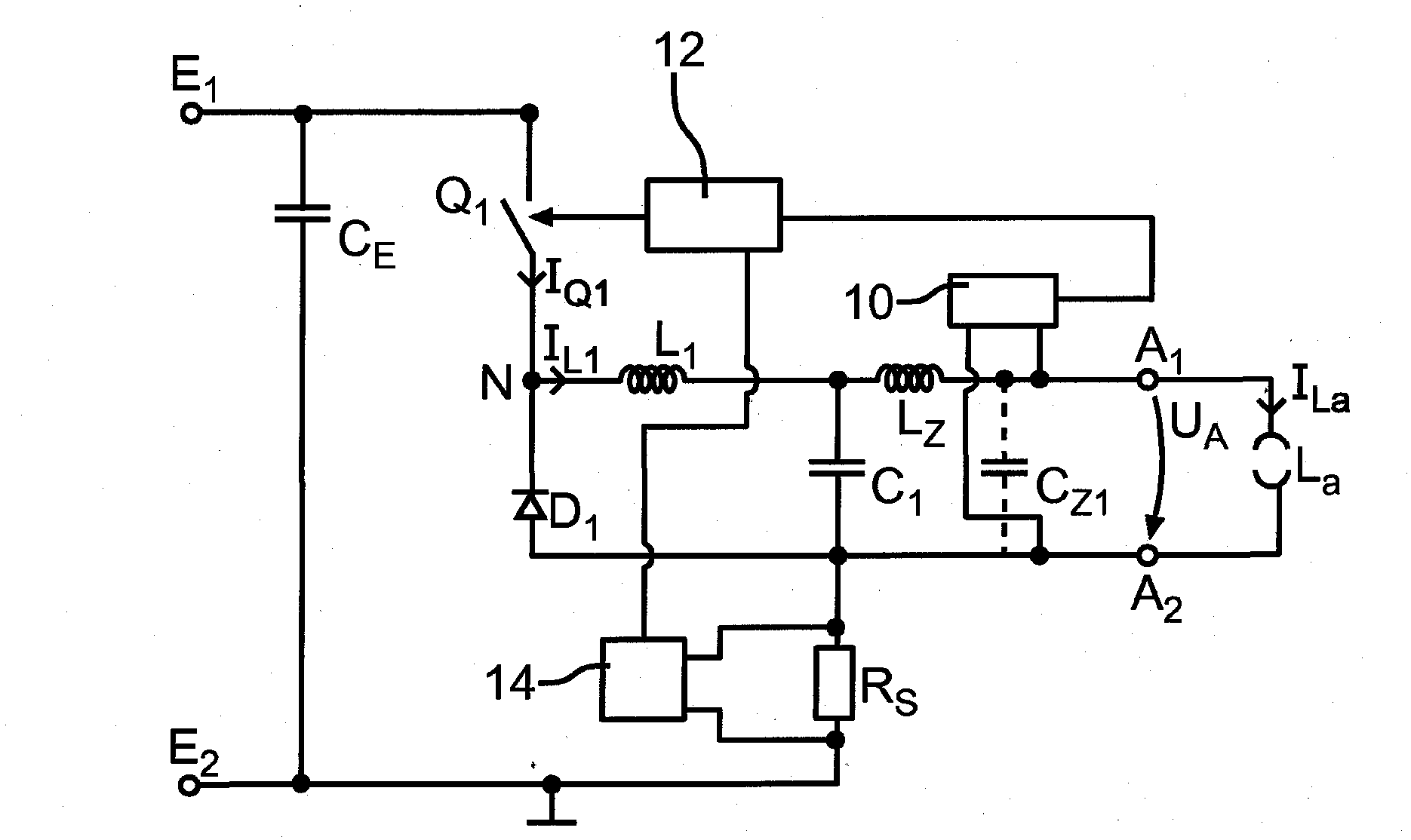
[0028] figure 1 A first exemplary embodiment of a circuit arrangement according to the invention is shown in a schematic diagram. The circuit arrangement comprises a first input terminal E with 1 and the second input terminal E 2 The input terminal to which the supply voltage can be connected. An optional capacitor C is provided between the inputs E , which is used to stabilize the input voltage. The circuit arrangement comprises a first electronic switch Q 1 , with control, working, and reference electrodes. Working electrode and first input terminal E 1 coupling. In addition, there is a diode D 1 , its negative pole is connected to the electronic switch Q 1 The reference electrodes of are coupled forming a connection point N. Furthermore, the circuit arrangement comprises a first output terminal A 1 and the second output terminal A 2 The output terminal, on which the output voltage U A Provided to the discharge lamp La. At the connection point N and the first o...


PUM


Abstract

The present invention relates to a circuit arrangement for operation of a discharge lamp, comprising: an input having a first input connection (E1) and a second input connection (E2) for connection of a supply voltage; a first electronic switch (Q1), which has a control electrode, a working electrode and a reference electrode, wherein the working electrode is coupled to the first input connection (E1); a first diode (D1), the anode of which is coupled to the second input (E2) and the cathode of which is coupled to the reference electrode of the first electronic switch (Q1) to form a first junction point (N); a control apparatus (12), which is coupled to the control electrode of the first electronic switch (Q1) in order to drive said first electronic switch (Q1); an output with a first output connection (A1) and a second output connection (A2) for providing an output voltage (UA) to the discharge lamp (La); an inductance (Lz), which is arranged in series with one of the output connections (A1; A2); a lamp inductor (L1), which is coupled between the first junction point (N) and the first output connection (A1); and a first capacitor (C1), which is coupled between the first output connection (A1) and the anode of the first diode (D1); wherein the control apparatus (12) is designed to switch the first electronic switch (Q1) on continuously for a switched-on time and to switch it off continuously for a switched-off time; wherein the circuit arrangement furthermore comprises a voltage measurement apparatus (10) for measuring the output voltage (UA), wherein the voltage measurement apparatus (10) is designed to produce at its output a signal which is correlated with the measured output voltage (UA) wherein the voltage measurement apparatus (10) is coupled to the control apparatus (12) in order to transmit this signal to the control apparatus (12), and wherein the control apparatus (12) is designed to vary the switched-off time (Toff) as a function of the measured output.

Description

technical field [0001] The invention relates to a circuit arrangement for operating a discharge lamp, comprising: an input with a first input terminal and a second input terminal for connecting a supply voltage; a first electronic switch with a control electrode, a working electrode and a reference electrode, wherein the working electrode is coupled to the first input terminal; a first diode, whose anode is coupled to the second input terminal and whose cathode is coupled to the reference electrode of the first electronic switch forming a first connection point; a control device coupled to the control electrode of the electronic switch for activating the first electronic switch; an output with a first output terminal and a second output terminal for supplying an output voltage to the discharge lamp; an inductor with one of the output terminals is arranged in series; a lamp inductor coupled between the first connection point and the first output terminal; and a first capacitor ...

Claims


Application Information

Patent Timeline
Patent Type & Authority Applications(China)
IPC IPC(8): H05B41/282H05B41/392
CPCH05B41/3925H05B41/2828H05B41/14H05B41/282H05B41/392
Inventor 阿洛伊斯·布朗恩沃尔特·利默马克西米利安·施米德尔
Owner OSRAM GMBH
Why Eureka
Try Eureka