Solar energy high-temperature heat collecting pipe exhaust method used for generating electricity and horizontal-type exhaust platform

An exhaust method and a technology of heat collecting tubes, which are applied in the directions of solar thermal power generation, solar thermal devices, heating devices, etc., can solve the problems that cannot meet the requirements of high temperature heat collecting tubes for solar power generation, and the heat conduction temperature is not high, so as to save auxiliary working time, The production cycle is compact and the effect of ensuring the quality of the workmanship

Inactive Publication Date: 2011-08-24
衡阳市真空机电设备有限公司
View PDF7 Cites 6 Cited by
  • Summary
  • Abstract
  • Description
  • Claims
  • Application Information

AI Technical Summary

Problems solved by technology

[0002] At present, the most common collector tube exhaust units in the domestic market are all vertical structures. The length of the medium and low temperature collector tubes produced is mostly within 1.5-2.1 meters. The structure is double-layer single-ended opening, and water is used as the heat transfer medium. The heat conduction temperature requirement is not high, it is mainly used in solar water heaters and other hot water projects, and cannot meet the needs of high temperature collector tubes for solar power generation

Method used


Image

  • Solar energy high-temperature heat collecting pipe exhaust method used for generating electricity and horizontal-type exhaust platform
  • Solar energy high-temperature heat collecting pipe exhaust method used for generating electricity and horizontal-type exhaust platform
  • Solar energy high-temperature heat collecting pipe exhaust method used for generating electricity and horizontal-type exhaust platform

Examples


Embodiment Construction

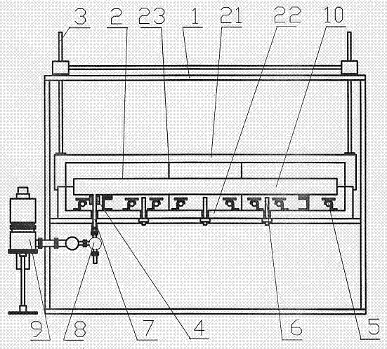
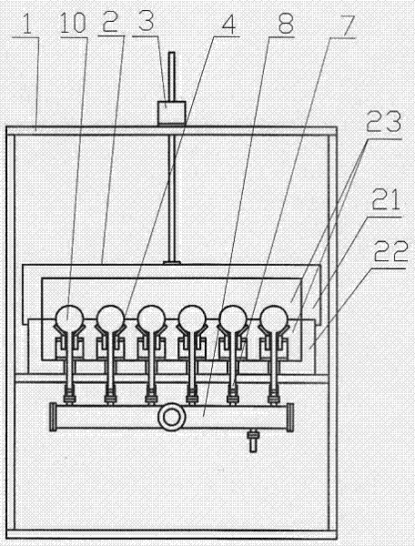
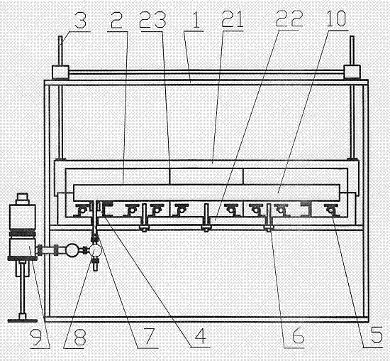
[0023] Such as figure 1 , 2 Shown: A solar high-temperature heat collection tube horizontal exhaust platform for power generation, including a frame 1, an incubator 2, a lifting mechanism 3, an electric heating sealing furnace 4, an electric heating tube 5, a thermocouple 6, a vacuum hose 7, an exhaust The main pipe 8 and the molecular pump vacuum system 9, the insulation box 2 adopts a horizontal rectangular box structure, which has good heat insulation and heat preservation functions, and two layers of stainless steel reflectors are added inside to reduce heat radiation and improve heat preservation performance. The insulation material is filled between them. The insulation box 2 is divided into two parts, the upper box body 21 and the lower box body 22. The inside of the box is separated into three temperature control areas by a partition 23. The temperature of each temperature control area can be set according to the process requirements. and adjustment, the temperature o...


PUM


Abstract

The invention discloses a solar energy high-temperature heat collecting pipe horizontal-type exhaust platform, comprising a rack (1), a heat preservation box (2), a lifting mechanism (3), an electric heating sealing furnace (4), an electric heating pipe (5), a thermocouple (6), a vacuum plastic tube (7), an exhaust header pipe (8) and a molecular pump vacuum air suction system (9), wherein, a horizontal-type square box body structure is adopted for the heat preservation box (2) which is divided into an upper box body (21) and a lower box body (22); the box body is separated into three temperature control areas by a clapboard (23); the electric heating sealing furnace (4) and a stainless steel vertical-tube electric heating pipe (5) are arranged on the base plate of the lower box body (22); an armoured thermocouple (6) is arranged in the heat preservation box (2) for detecting the temperature in the box; the molecular pump vacuum air suction system (9) is connected with the tail end of a high-temperature heat collecting pipe (10) through the exhaust header pipe (8) and the vacuum plastic tube (7), so as to carry out roasting and exhausting. In the invention, the existing heat collecting pipe exhaust platform vertical structure is changed into a horizontal-type structure, thus the difficulties that the equipment and the workshop are ultrahigh, as well as the use, the maintenance, the assembling and the disassembling of the workpieces are difficult caused by exhausting by a ultralong pipe are solved, thus creating condition for automation implementing.

Description

technical field [0001] The invention relates to a special equipment for vacuum exhaust, in particular to an exhaust method of a solar high-temperature heat collection tube for power generation and a horizontal exhaust platform. Background technique [0002] At present, the most common collector tube exhaust units in the domestic market are all vertical structures. The length of the medium and low temperature collector tubes produced is mostly within 1.5-2.1 meters. The structure is double-layer single-ended opening, and water is used as the heat transfer medium. The heat conduction temperature requirement is not high, and it is mainly used in solar water heaters and other hot water projects, which cannot meet the needs of high-temperature heat collecting tubes for solar power generation. The structure of the high-temperature vacuum heat collector tube for power generation is double-layer double-ended opening. It is coated with a light-selective absorbing coating on the alloy...

Claims


Application Information

Patent Timeline
Patent Type & Authority Applications(China)
IPC IPC(8): F24J2/48C03B23/057
CPCY02E10/40
Inventor 李云辉李云松华冬辉
Owner 衡阳市真空机电设备有限公司
Why Eureka
Try Eureka