Parking device of electric automobile

A technology for electric vehicles and parking, applied in electric vehicles, electric brake systems, brakes, etc., can solve the problems of complex structure, high manufacturing difficulty, and large quantity, and achieve good assembly process, low processing difficulty, and technological content high effect

Active Publication Date: 2012-10-10
ZHEJIANG GEELY AUTOMOBILE RES INST CO LTD +1
View PDF1 Cites 0 Cited by
  • Summary
  • Abstract
  • Description
  • Claims
  • Application Information

AI Technical Summary

Problems solved by technology

[0004] Although the above-mentioned electric parking brake realizes the parking function through the power source, it also has the following disadvantages: the parking brake controls the gear meshing and locking the brake by pulling the cable, so that the braking force is weak and the force is stable. Poor performance, low immediacy of locking, complex structure, large number of parts and components, poor assembly and integration, resulting in a large assembly workload of the transmission assembly; large space requirements for the layout of the entire mechanism; poor assembly process and low safety performance
[0005] At the same time, in the existing parking devices of the same kind, the positioning rail plate and flat spring of the parts that provide gear position perception are complex in structure, and the positioning rail plate requires fine blanking or powder metallurgy, which is difficult to manufacture and complicated to manage suppliers; the torsion spring torque alone Unable to guarantee a stable return force of the pawl, making its function unreliable; the limit structure of the actuator lever assembly is complicated, and the assembly process of the parking ratchet and the differential is poor

Method used


Image

  • Parking device of electric automobile
  • Parking device of electric automobile
  • Parking device of electric automobile

Examples


Embodiment Construction

[0023] The following are specific embodiments of the present invention and in conjunction with the accompanying drawings, the technical solutions of the present invention are further described, but the present invention is not limited to these embodiments.

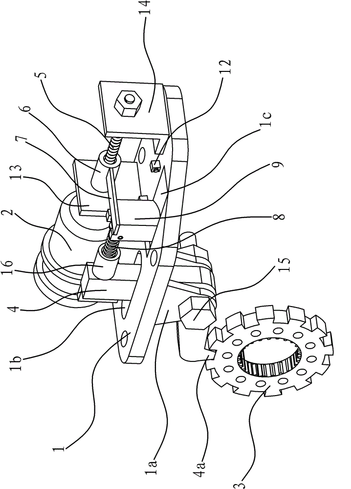
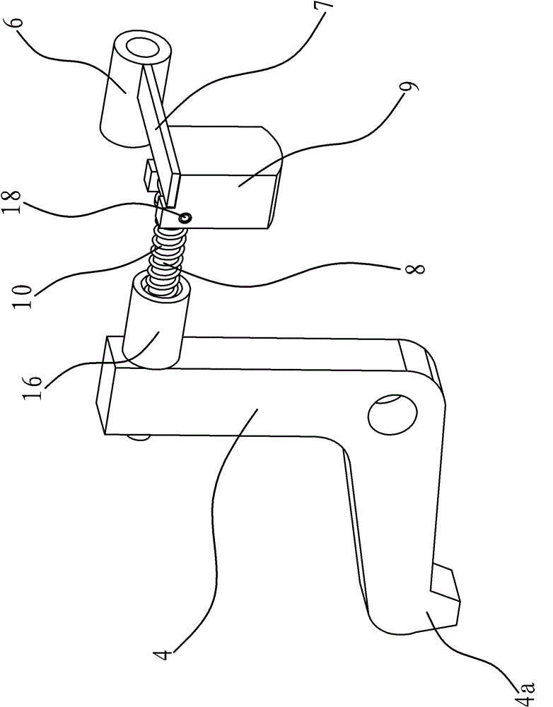
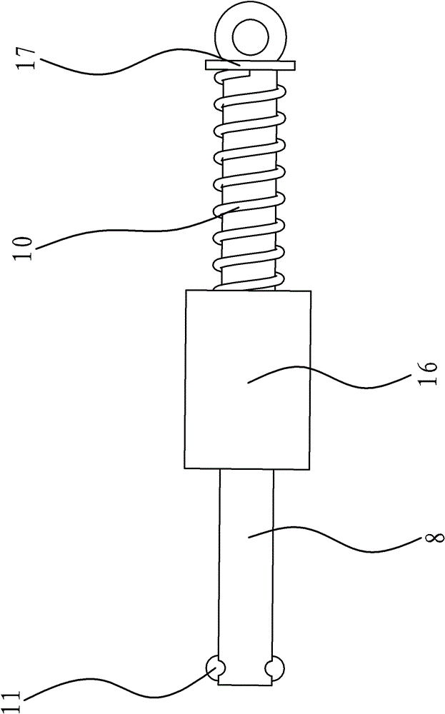
[0024] Such as figure 1 , figure 2 with image 3 As shown, the electric vehicle parking device comprises a mounting plate 1 and a motor 2 located on the mounting plate 1, the wheel shaft of the automobile is fixed with a parking gear 3 in the circumferential direction, and the mounting plate 1 is provided with a parking gear 3 that can be connected with the parking gear 3. The ratchet 4 that cooperates, motor 2 drives the ratchet 4 to swing through a control mechanism to realize the conversion between the two modes of the working end of the ratchet 4 being embedded and disengaged from the teeth of the parking gear 3 .

[0025] The motor 2 is a DC12V small motor, and it can directly use the battery of the whole vehicle a...


PUM


Abstract

The invention provides a parking device of an electric automobile, belonging to the technical field of an automobile, and solving the problems that an existing electric parking brake is weaker in braking application force, poor in acting force stability, low in locking instantaneity, complex in structure, poor in assembly performance and integration performance, and the like. The parking device of the electric automobile comprises an mounting plate and a motor arranged on the mounting plate, wherein a parking gear is fixed around a wheel axle of the automobile, a pawl matched with the packinggear is arranged on the mounting plate, a control mechanism is arranged between the motor and the pawl, and the pawl is driven by the motor through the control mechanism to swing, so that the mode that a working end of the pawl is embedded into parking gear teeth and the mode that the working end of the pawl is departed from the parking gear teeth can transform from each other. The parking deviceof the electric automobile is an electrical and mechanical integrated high-tech integration device, so that the device is high in technological content, simple, compact, safe and reliable in structure, high in transmission efficiency, timely in effect, good in effect, convenient to install, low in machining difficulty, and good in assembly technology.

Description

technical field [0001] The invention belongs to the technical field of automobiles, and relates to a parking device, in particular to a parking device for an electric vehicle. Background technique [0002] With the two major problems of environmental pollution and energy shortage becoming more and more serious in today's world, governments of various countries have introduced preferential policies to promote the rapid development of the electric vehicle industry, and major car companies have also increased investment in the production and research and development of electric vehicles. Various electric vehicles. As an energy-saving, environmentally friendly and high-tech electric vehicle, its safety performance is particularly important, and the requirements for the parking device, a safety device that prevents the vehicle from sliding, are becoming more and more stringent. [0003] For example, Chinese patent literature once disclosed an electric parking brake [Chinese pate...

Claims


Application Information

Patent Timeline
Patent Type & Authority Patents(China)
IPC IPC(8): B60L7/24B60T1/06
Inventor 雷宇陈勇罗大国范钰琢赵福全
Owner ZHEJIANG GEELY AUTOMOBILE RES INST CO LTD
Why Eureka
Try Eureka